LFEBS12UB Freescale Semiconductor, LFEBS12UB Datasheet - Page 1243
LFEBS12UB
Manufacturer Part Number
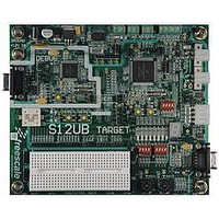
LFEBS12UB
Description
KIT STUDENT LEARNING S12 DG128
Manufacturer
Freescale Semiconductor
Specifications of LFEBS12UB
Architecture
8/16-bit
Code Gen Tools Included
Code Warrior
Silicon Manufacturer
Freescale
Core Architecture
S12
Core Sub-architecture
S12
Silicon Core Number
MC9S12
Silicon Family Name
S12D
Kit Contents
HCS12 DG128 Learning Kit
Rohs Compliant
Yes
Lead Free Status / RoHS Status
Lead free / RoHS Compliant


1
A.7.2.1
In
Freescale Semiconductor
Drive mode
Load capacitance C
Thresholds for delay measurement points
Timing specified for equal load on all SPI output pins. Avoid asymmetric load.
Figure A-7
(CPOL = 1)
(CPOL = 0)
(Output)
(Output)
(Output)
(Output)
1. If configured as an output.
2. LSBF = 0. For LSBF = 1, bit order is LSB, bit 1, bit 2... MSB.
(Input)
MISO
MOSI
SCK
SCK
SS1
Master Mode
the timing diagram for master mode with transmission format CPHA = 0 is depicted.
LOAD
1
,
on all outputs
2
5
10
MSB IN2
MSB OUT2
Description
MC9S12XE-Family Reference Manual Rev. 1.23
6
Figure A-7. SPI Master Timing (CPHA = 0)
4
Table A-27. Measurement Conditions
1
Bit MSB-1. . . 1
4
Bit MSB-1. . . 1
9
12
12
LSB IN
LSB OUT
13
13
(20% / 80%) V
Full drive mode
Appendix A Electrical Characteristics
Value
50
11
3
DDX
Unit
pF
—
V
1243
Related parts for LFEBS12UB
Image
Part Number
Description
Manufacturer
Datasheet
Request
R

Part Number:
Description:
Manufacturer:
Freescale Semiconductor, Inc
Datasheet:
Part Number:
Description:
Manufacturer:
Freescale Semiconductor, Inc
Datasheet:
Part Number:
Description:
Manufacturer:
Freescale Semiconductor, Inc
Datasheet:
Part Number:
Description:
Manufacturer:
Freescale Semiconductor, Inc
Datasheet:
Part Number:
Description:
Manufacturer:
Freescale Semiconductor, Inc
Datasheet:
Part Number:
Description:
Manufacturer:
Freescale Semiconductor, Inc
Datasheet:
Part Number:
Description:
Manufacturer:
Freescale Semiconductor, Inc
Datasheet:
Part Number:
Description:
Manufacturer:
Freescale Semiconductor, Inc
Datasheet:
Part Number:
Description:
Manufacturer:
Freescale Semiconductor, Inc
Datasheet:
Part Number:
Description:
Manufacturer:
Freescale Semiconductor, Inc
Datasheet:
Part Number:
Description:
Manufacturer:
Freescale Semiconductor, Inc
Datasheet:
Part Number:
Description:
Manufacturer:
Freescale Semiconductor, Inc
Datasheet:
Part Number:
Description:
Manufacturer:
Freescale Semiconductor, Inc
Datasheet:
Part Number:
Description:
Manufacturer:
Freescale Semiconductor, Inc
Datasheet:
Part Number:
Description:
Manufacturer:
Freescale Semiconductor, Inc
Datasheet: