LFEBS12UB Freescale Semiconductor, LFEBS12UB Datasheet - Page 517
LFEBS12UB
Manufacturer Part Number
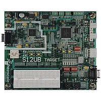
LFEBS12UB
Description
KIT STUDENT LEARNING S12 DG128
Manufacturer
Freescale Semiconductor
Specifications of LFEBS12UB
Architecture
8/16-bit
Code Gen Tools Included
Code Warrior
Silicon Manufacturer
Freescale
Core Architecture
S12
Core Sub-architecture
S12
Silicon Core Number
MC9S12
Silicon Family Name
S12D
Kit Contents
HCS12 DG128 Learning Kit
Rohs Compliant
Yes
Lead Free Status / RoHS Status
Lead free / RoHS Compliant


13.3.2.6
Writes to this register will abort current conversion sequence and start a new conversion sequence. If
external trigger is enabled (ETRIGE=1) an initial write to ATDCTL5 is required to allow starting of a
conversion sequence which will then occur on each trigger event. Start of conversion means the beginning
of the sampling phase.
Read: Anytime
Write: Anytime
Freescale Semiconductor
Module Base + 0x0005
Because of an order from the United States International Trade Commission, BGA-packaged product lines and partnumbers
SMP[2:0]
PRS[4:0]
Reset
indicated here currently are not available from Freescale for import or sale in the United States prior to September 2010
Field
7–5
4–0
W
R
Sample Time Select — These three bits select the length of the sample time in units of ATD conversion clock
cycles. Note that the ATD conversion clock period is itself a function of the prescaler value (bits PRS4-0).
Table 13-14
ATD Clock Prescaler — These 5 bits are the binary prescaler value PRS. The ATD conversion clock frequency
is calculated as follows:
Refer to Device Specification for allowed frequency range of f
ATD Control Register 5 (ATDCTL5)
0
0
7
lists the available sample time lengths.
f ATDCLK
SMP2
SC
0
6
0
0
0
0
1
1
1
1
Figure 13-8. ATD Control Register 5 (ATDCTL5)
MC9S12XE-Family Reference Manual Rev. 1.23
Table 13-13. ATDCTL4 Field Descriptions
=
------------------------------------ -
2
SMP1
SCAN
×
Table 13-14. Sample Time Select
(
0
0
1
1
0
0
1
1
5
0
f BUS
PRS
+
1
)
SMP0
MULT
0
1
0
1
0
1
0
1
0
4
Description
ATD Clock Cycles
Chapter 13 Analog-to-Digital Converter (ADC12B16CV1)
CD
0
3
Sample Time
in Number of
ATDCLK
10
12
16
20
24
4
6
8
.
CC
2
0
CB
0
1
CA
0
0
517
Related parts for LFEBS12UB
Image
Part Number
Description
Manufacturer
Datasheet
Request
R

Part Number:
Description:
Manufacturer:
Freescale Semiconductor, Inc
Datasheet:
Part Number:
Description:
Manufacturer:
Freescale Semiconductor, Inc
Datasheet:
Part Number:
Description:
Manufacturer:
Freescale Semiconductor, Inc
Datasheet:
Part Number:
Description:
Manufacturer:
Freescale Semiconductor, Inc
Datasheet:
Part Number:
Description:
Manufacturer:
Freescale Semiconductor, Inc
Datasheet:
Part Number:
Description:
Manufacturer:
Freescale Semiconductor, Inc
Datasheet:
Part Number:
Description:
Manufacturer:
Freescale Semiconductor, Inc
Datasheet:
Part Number:
Description:
Manufacturer:
Freescale Semiconductor, Inc
Datasheet:
Part Number:
Description:
Manufacturer:
Freescale Semiconductor, Inc
Datasheet:
Part Number:
Description:
Manufacturer:
Freescale Semiconductor, Inc
Datasheet:
Part Number:
Description:
Manufacturer:
Freescale Semiconductor, Inc
Datasheet:
Part Number:
Description:
Manufacturer:
Freescale Semiconductor, Inc
Datasheet:
Part Number:
Description:
Manufacturer:
Freescale Semiconductor, Inc
Datasheet:
Part Number:
Description:
Manufacturer:
Freescale Semiconductor, Inc
Datasheet:
Part Number:
Description:
Manufacturer:
Freescale Semiconductor, Inc
Datasheet: