LFEBS12UB Freescale Semiconductor, LFEBS12UB Datasheet - Page 518
LFEBS12UB
Manufacturer Part Number
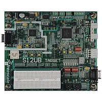
LFEBS12UB
Description
KIT STUDENT LEARNING S12 DG128
Manufacturer
Freescale Semiconductor
Specifications of LFEBS12UB
Architecture
8/16-bit
Code Gen Tools Included
Code Warrior
Silicon Manufacturer
Freescale
Core Architecture
S12
Core Sub-architecture
S12
Silicon Core Number
MC9S12
Silicon Family Name
S12D
Kit Contents
HCS12 DG128 Learning Kit
Rohs Compliant
Yes
Lead Free Status / RoHS Status
Lead free / RoHS Compliant


Chapter 13 Analog-to-Digital Converter (ADC12B16CV1)
518
Because of an order from the United States International Trade Commission, BGA-packaged product lines and partnumbers
CD, CC,
CB, CA
SCAN
indicated here currently are not available from Freescale for import or sale in the United States prior to September 2010
MULT
Field
3–0
SC
6
5
4
Special Channel Conversion Bit — If this bit is set, then special channel conversion can be selected using CD,
CC, CB and CA of ATDCTL5.
0 Special channel conversions disabled
1 Special channel conversions enabled
Continuous Conversion Sequence Mode — This bit selects whether conversion sequences are performed
continuously or only once. If external trigger is enabled (ETRIGE=1) setting this bit has no effect, that means
external trigger always starts a single conversion sequence.
0 Single conversion sequence
1 Continuous conversion sequences (scan mode)
Multi-Channel Sample Mode — When MULT is 0, the ATD sequence controller samples only from the specified
analog input channel for an entire conversion sequence. The analog channel is selected by channel selection
code (control bits CD/CC/CB/CA located in ATDCTL5). When MULT is 1, the ATD sequence controller samples
across channels. The number of channels sampled is determined by the sequence length value (S8C, S4C, S2C,
S1C). The first analog channel examined is determined by channel selection code (CD, CC, CB, CA control bits);
subsequent channels sampled in the sequence are determined by incrementing the channel selection code or
wrapping around to AN0 (channel 0).
0 Sample only one channel
1 Sample across several channels
Analog Input Channel Select Code — These bits select the analog input channel(s) whose signals are
sampled and converted to digital codes.
channels.
In the case of single channel conversions (MULT=0), this selection code specifies the channel to be examined.
In the case of multiple channel conversions (MULT=1), this selection code specifies the first channel to be
examined in the conversion sequence. Subsequent channels are determined by incrementing the channel
selection code or wrapping around to AN0 (after converting the channel defined by the Wrap Around Channel
Select Bits WRAP3-0 in ATDCTL0). In case of starting with a channel number higher than the one defined by
WRAP3-0 the first wrap around will be AN15 to AN0.
MC9S12XE-Family Reference Manual , Rev. 1.23
Table 13-15. ATDCTL5 Field Descriptions
Table 13-16
Table 13-16
lists the coding.
Description
lists the coding used to select the various analog input
Freescale Semiconductor
Related parts for LFEBS12UB
Image
Part Number
Description
Manufacturer
Datasheet
Request
R

Part Number:
Description:
Manufacturer:
Freescale Semiconductor, Inc
Datasheet:
Part Number:
Description:
Manufacturer:
Freescale Semiconductor, Inc
Datasheet:
Part Number:
Description:
Manufacturer:
Freescale Semiconductor, Inc
Datasheet:
Part Number:
Description:
Manufacturer:
Freescale Semiconductor, Inc
Datasheet:
Part Number:
Description:
Manufacturer:
Freescale Semiconductor, Inc
Datasheet:
Part Number:
Description:
Manufacturer:
Freescale Semiconductor, Inc
Datasheet:
Part Number:
Description:
Manufacturer:
Freescale Semiconductor, Inc
Datasheet:
Part Number:
Description:
Manufacturer:
Freescale Semiconductor, Inc
Datasheet:
Part Number:
Description:
Manufacturer:
Freescale Semiconductor, Inc
Datasheet:
Part Number:
Description:
Manufacturer:
Freescale Semiconductor, Inc
Datasheet:
Part Number:
Description:
Manufacturer:
Freescale Semiconductor, Inc
Datasheet:
Part Number:
Description:
Manufacturer:
Freescale Semiconductor, Inc
Datasheet:
Part Number:
Description:
Manufacturer:
Freescale Semiconductor, Inc
Datasheet:
Part Number:
Description:
Manufacturer:
Freescale Semiconductor, Inc
Datasheet:
Part Number:
Description:
Manufacturer:
Freescale Semiconductor, Inc
Datasheet: