LFEBS12UB Freescale Semiconductor, LFEBS12UB Datasheet - Page 286
LFEBS12UB
Manufacturer Part Number
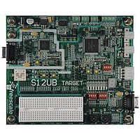
LFEBS12UB
Description
KIT STUDENT LEARNING S12 DG128
Manufacturer
Freescale Semiconductor
Specifications of LFEBS12UB
Architecture
8/16-bit
Code Gen Tools Included
Code Warrior
Silicon Manufacturer
Freescale
Core Architecture
S12
Core Sub-architecture
S12
Silicon Core Number
MC9S12
Silicon Family Name
S12D
Kit Contents
HCS12 DG128 Learning Kit
Rohs Compliant
Yes
Lead Free Status / RoHS Status
Lead free / RoHS Compliant


Chapter 7 Background Debug Module (S12XBDMV2)
Read: All modes through BDM operation when not secured
Write: All modes through BDM operation when not secured, but subject to the following:
286
Because of an order from the United States International Trade Commission, BGA-packaged product lines and partnumbers
BDMACT
ENBDM
TRACE
indicated here currently are not available from Freescale for import or sale in the United States prior to September 2010
Field
SDV
7
6
4
3
— ENBDM should only be set via a BDM hardware command if the BDM firmware commands
— BDMACT can only be set by BDM hardware upon entry into BDM. It can only be cleared by
— CLKSW can only be written via BDM hardware WRITE_BD commands.
— All other bits, while writable via BDM hardware or standard BDM firmware write commands,
are needed. (This does not apply in special single chip and emulation modes).
the standard BDM firmware lookup table upon exit from BDM active mode.
should only be altered by the BDM hardware or standard firmware lookup table as part of BDM
command execution.
Enable BDM — This bit controls whether the BDM is enabled or disabled. When enabled, BDM can be made
active to allow firmware commands to be executed. When disabled, BDM cannot be made active but BDM
hardware commands are still allowed.
0 BDM disabled
1 BDM enabled
Note: ENBDM is set by the firmware out of reset in special single chip mode. In emulation modes (if modes
BDM Active Status — This bit becomes set upon entering BDM. The standard BDM firmware lookup table is
then enabled and put into the memory map. BDMACT is cleared by a carefully timed store instruction in the
standard BDM firmware as part of the exit sequence to return to user code and remove the BDM memory from
the map.
0 BDM not active
1 BDM active
Shift Data Valid — This bit is set and cleared by the BDM hardware. It is set after data has been transmitted as
part of a firmware or hardware read command or after data has been received as part of a firmware or hardware
write command. It is cleared when the next BDM command has been received or BDM is exited. SDV is used
by the standard BDM firmware to control program flow execution.
0 Data phase of command not complete
1 Data phase of command is complete
TRACE1 BDM Firmware Command is Being Executed — This bit gets set when a BDM TRACE1 firmware
command is first recognized. It will stay set until BDM firmware is exited by one of the following BDM commands:
GO or GO_UNTIL.
0 TRACE1 command is not being executed
1 TRACE1 command is being executed
available) the ENBDM bit is set by BDM hardware out of reset. In special single chip mode with the device
secured, this bit will not be set by the firmware until after the non-volatile memory erase verify tests are
complete. In emulation modes (if modes available) with the device secured, the BDM operations are
blocked.
MC9S12XE-Family Reference Manual , Rev. 1.23
Table 7-3. BDMSTS Field Descriptions
Description
Freescale Semiconductor
Related parts for LFEBS12UB
Image
Part Number
Description
Manufacturer
Datasheet
Request
R

Part Number:
Description:
Manufacturer:
Freescale Semiconductor, Inc
Datasheet:
Part Number:
Description:
Manufacturer:
Freescale Semiconductor, Inc
Datasheet:
Part Number:
Description:
Manufacturer:
Freescale Semiconductor, Inc
Datasheet:
Part Number:
Description:
Manufacturer:
Freescale Semiconductor, Inc
Datasheet:
Part Number:
Description:
Manufacturer:
Freescale Semiconductor, Inc
Datasheet:
Part Number:
Description:
Manufacturer:
Freescale Semiconductor, Inc
Datasheet:
Part Number:
Description:
Manufacturer:
Freescale Semiconductor, Inc
Datasheet:
Part Number:
Description:
Manufacturer:
Freescale Semiconductor, Inc
Datasheet:
Part Number:
Description:
Manufacturer:
Freescale Semiconductor, Inc
Datasheet:
Part Number:
Description:
Manufacturer:
Freescale Semiconductor, Inc
Datasheet:
Part Number:
Description:
Manufacturer:
Freescale Semiconductor, Inc
Datasheet:
Part Number:
Description:
Manufacturer:
Freescale Semiconductor, Inc
Datasheet:
Part Number:
Description:
Manufacturer:
Freescale Semiconductor, Inc
Datasheet:
Part Number:
Description:
Manufacturer:
Freescale Semiconductor, Inc
Datasheet:
Part Number:
Description:
Manufacturer:
Freescale Semiconductor, Inc
Datasheet: