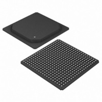
DS3163 Maxim Integrated Products, DS3163 Datasheet - Page 11

DS3163
Manufacturer Part Number
DS3163
Description
IC TRPL ATM/PACKET PHY 400-PBGA
Manufacturer
Maxim Integrated Products
Datasheet
1.DS3163.pdf
(384 pages)
Specifications of DS3163
Applications
*
Mounting Type
Surface Mount
Package / Case
400-BGA
Lead Free Status / RoHS Status
Lead free / RoHS Compliant
Available stocks
Company
Part Number
Manufacturer
Quantity
Price
- Current page: 11 of 384
- Download datasheet (4Mb)
DS3161/DS3162/DS3163/DS3164
LIST OF TABLES
Table 4-1. Standards Compliance ............................................................................................................................. 22
Table 6-1. DS3/E3 ATM/Packet Mode Configuration Registers................................................................................ 25
Table 6-2. DS3/E3 ATM/Packet—OHM Mode Configuration Registers.................................................................... 26
Table 6-3. DS3/E3 Internal Fractional (IFRAC) ATM/Packet Mode Configuration Registers ................................... 27
Table 6-4. DS3/E3 External Fractional (XFRAC) ATM/Packet Mode Configuration Registers................................. 28
Table 6-5. DS3/E3 Flexible External Fractional (Subrate) Mode Configuration Registers........................................ 29
Table 6-6. DS3/E3 G.751 PLCP ATM Mode Configuration Registers ...................................................................... 30
Table 6-7. DS3/E3 G.751 PLCP ATM—OHM Mode Configuration Registers .......................................................... 31
Table 6-8. Clear-Channel ATM/Packet Mode Configuration Modes ......................................................................... 33
Table 6-9. Clear-Channel ATM/Packet—OHM Mode Configuration Registers......................................................... 34
Table 6-10. Clear-Channel Octet Aligned ATM/Packet—OHM Mode Configuration Registers................................ 35
Table 7-1. HDB3/B3ZS/AMI Mode Configuration Registers...................................................................................... 36
Table 7-2. UNI Line Interface Mode Configuration Registers.................................................................................... 37
Table 7-3. UNI Line Interface—OHM Mode Configuration Registers........................................................................ 38
Table 8-1. DS3164 Short Pin Descriptions............................................................................................................... 39
Table 8-2. Detailed Pin Descriptions ......................................................................................................................... 44
Table 9-1. Configuration of Global Register Settings ................................................................................................ 92
Table 9-2. Configuration of Port Register Settings .................................................................................................... 92
Table 10-1. All Possible Clock Sources Based on Mode and Loopback................................................................... 98
Table 10-2. Source Selection of TLCLK Clock Signal ............................................................................................... 98
Table 10-3. Source Selection of TCLKOn (internal TX clock) ................................................................................... 99
Table 10-4. Source Selection of RCLKO Clock Signal (internal RX clock) ............................................................... 99
Table 10-5. Transmit Line Interface Signal Pin Valid Timing Source Select ........................................................... 100
Table 10-6. Transmit Framer Pin Signal Timing Source Select .............................................................................. 101
Table 10-7. Receive Framer Pin Signal Timing Source Select ............................................................................... 101
Table 10-8. Reset and Power-Down Sources ......................................................................................................... 104
Table 10-9. CLAD IO Pin Decode............................................................................................................................ 107
Table 10-10. Global 8kHz Reference Source Table................................................................................................ 108
Table 10-11. Port 8kHz Reference Source Table.................................................................................................... 108
Table 10-12. GPIO Global Signals .......................................................................................................................... 110
Table 10-13. GPIO Pin Global Mode Select Bits..................................................................................................... 110
Table 10-14. GPIO Port Alarm Monitor Select ........................................................................................................ 110
Table 10-15. Loopback Mode Selections ................................................................................................................ 112
Table 10-16. Line AIS Enable Modes ...................................................................................................................... 116
Table 10-17. Payload (downstream) AIS Enable Modes......................................................................................... 116
Table 10-18. TSOFIn / TOHMIn Input Pin Functions .............................................................................................. 117
Table 10-19. TSERn / TPOHn / TFOHn Input Pin Functions .................................................................................. 118
Table 10-20. TPDENIn / TPOHENn / TFOHENIn Input Pin Functions ................................................................... 118
Table 10-21. TSOFOn / TDENn / TPOHSOFn / TFOHENOn Output Pin Functions .............................................. 118
Table 10-22. TCLKOn / TGCLKn / TPOHCLKn Output Pin Functions.................................................................... 119
Table 10-23. TPDATn Input Pin Functions.............................................................................................................. 119
Table 10-24. TPDENOn Output Pin Functions........................................................................................................ 119
Table 10-25. RSERn / RPOHn Output Pin Functions ............................................................................................. 120
Table 10-26. RPDENIn / RFOHENIn Input Pin Functions....................................................................................... 120
Table 10-27. RPDATn Input Pin Functions ............................................................................................................. 120
Table 10-28. RSOFOn / RDENn / RPOHSOFn / RFOHENOn Output Pin Functions............................................. 121
Table 10-29. RCLKOn / RGCLKn / RPOHCLKn Output Pin Functions .................................................................. 121
Table 10-30. Framing Mode Select Bits FM[5:0] ..................................................................................................... 122
Table 10-31. Line Mode Select Bits - LM ................................................................................................................ 127
Table 10-32. C-Bit DS3 Frame Overhead Bit Definitions ........................................................................................ 165
Table 10-33. M23 DS3 Frame Overhead Bit Definitions ......................................................................................... 168
Table 10-34. G.832 E3 Frame Overhead Bit Definitions ......................................................................................... 173
Table 10-35. Payload Label Match Status............................................................................................................... 176
Table 10-36. Pseudo-Random Pattern Generation ................................................................................................. 191
Table 10-37. Repetitive Pattern Generation ............................................................................................................ 191
Related parts for DS3163
Image
Part Number
Description
Manufacturer
Datasheet
Request
R

Part Number:
Description:
MAX7528KCWPMaxim Integrated Products [CMOS Dual 8-Bit Buffered Multiplying DACs]
Manufacturer:
Maxim Integrated Products
Datasheet:

Part Number:
Description:
Single +5V, fully integrated, 1.25Gbps laser diode driver.
Manufacturer:
Maxim Integrated Products
Datasheet:

Part Number:
Description:
Single +5V, fully integrated, 155Mbps laser diode driver.
Manufacturer:
Maxim Integrated Products
Datasheet:

Part Number:
Description:
VRD11/VRD10, K8 Rev F 2/3/4-Phase PWM Controllers with Integrated Dual MOSFET Drivers
Manufacturer:
Maxim Integrated Products
Datasheet:

Part Number:
Description:
Highly Integrated Level 2 SMBus Battery Chargers
Manufacturer:
Maxim Integrated Products
Datasheet:

Part Number:
Description:
Current Monitor and Accumulator with Integrated Sense Resistor; ; Temperature Range: -40°C to +85°C
Manufacturer:
Maxim Integrated Products

Part Number:
Description:
TSSOP 14/A�/RS-485 Transceivers with Integrated 100O/120O Termination Resis
Manufacturer:
Maxim Integrated Products

Part Number:
Description:
TSSOP 14/A�/RS-485 Transceivers with Integrated 100O/120O Termination Resis
Manufacturer:
Maxim Integrated Products

Part Number:
Description:
QFN 16/A�/AC-DC and DC-DC Peak-Current-Mode Converters with Integrated Step
Manufacturer:
Maxim Integrated Products

Part Number:
Description:
TDFN/A/65V, 1A, 600KHZ, SYNCHRONOUS STEP-DOWN REGULATOR WITH INTEGRATED SWI
Manufacturer:
Maxim Integrated Products

Part Number:
Description:
Integrated Temperature Controller f
Manufacturer:
Maxim Integrated Products

Part Number:
Description:
SOT23-6/I�/45MHz to 650MHz, Integrated IF VCOs with Differential Output
Manufacturer:
Maxim Integrated Products

Part Number:
Description:
SOT23-6/I�/45MHz to 650MHz, Integrated IF VCOs with Differential Output
Manufacturer:
Maxim Integrated Products

Part Number:
Description:
EVALUATION KIT/2.4GHZ TO 2.5GHZ 802.11G/B RF TRANSCEIVER WITH INTEGRATED PA
Manufacturer:
Maxim Integrated Products

Part Number:
Description:
QFN/E/DUAL PCIE/SATA HIGH SPEED SWITCH WITH INTEGRATED BIAS RESISTOR
Manufacturer:
Maxim Integrated Products
Datasheet:


