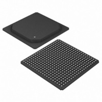
DS3163 Maxim Integrated Products, DS3163 Datasheet - Page 346

DS3163
Manufacturer Part Number
DS3163
Description
IC TRPL ATM/PACKET PHY 400-PBGA
Manufacturer
Maxim Integrated Products
Datasheet
1.DS3163.pdf
(384 pages)
Specifications of DS3163
Applications
*
Mounting Type
Surface Mount
Package / Case
400-BGA
Lead Free Status / RoHS Status
Lead free / RoHS Compliant
Available stocks
Company
Part Number
Manufacturer
Quantity
Price
- Current page: 346 of 384
- Download datasheet (4Mb)
Bit 0: Transmit Pass-Through Enable (TPTE) – When 0, pass-through mode is disabled and packet processing
is enabled. When 1, the packet processor is in pass-through mode and all packet processing functions except
scrambling and bit reordering are disabled.
Register Name:
Register Description:
Register Address:
Bit #
Name
Default
Bit #
Name
Default
Bits 7 to 0: Transmit Inter-Frame Gapping (TIFG[7:0]) – These eight bits indicate the number of additional flags
and bytes of inter-frame fill to be inserted between packets. The number of flags and bytes of inter-frame fill
between packets will be at least the value of TIFG[7:0] plus 1. Note: If inter-frame fill is set to all 1’s, a TFIG value
of 2 or 3 will result in a flag, at least two bytes of 1’s, and a flag between packets.
Register Name:
Register Description:
Register Address:
Bit #
Name
Default
Bit #
Name
Default
Bit 15: Manual Error Insert Mode Select (MEIMS) – When 0, the transmit manual error insertion signal (TMEI)
will not cause errors to be inserted. When 1, TMEI will causes an error to be inserted when it transitions from a 0 to
a 1. Note: Enabling TMEI does not disable error insertion using TPER[6:0] and TPEN[7:0].
Manual Error Insertion is available at the global level but not on a per port basis for the packet processor.
(PORT.CR1.MEIM must be set for global error insertion to insert a packet error.)
Bits 14 to 8: Transmit Errored Packet Insertion Rate (TPER[6:0]) – These seven bits indicate the rate at which
errored packets are to be output. One out of every x * 10
value x, and TPER[6:4] is the value y, which has a maximum value of 6. If TPER[3:0] has a value of 0h errored
packet insertion is disabled. If TPER[6:4] has a value of 6xh or 7xh the errored packet rate will be x * 10
TPER[6:0] value of 01h results in every packet being errored. A TPER[6:0] value of 0Fh results in every 15
being errored. A TPER[6:0] value of 11h result in every 10
when the PP.TEPC register is written with a TPER[3:0] value that is non-zero. If the PP.TEPC register is written to
during the middle of an errored packet insertion process, the current process is halted, and a new process will be
started using the new values of TPER[6:0] and TPEN[7:0}. Errored packet insertion ends when TPEN[7:0] errored
packets have been transmitted.
Bits 7 to 0: Transmit Errored Packet Insertion Number (TPEN[7:0]) – These eight bits indicate the total number
of errored packets to be transmitted. A value of FFh results in continuous errored packet insertion at the specified
rate.
MEIMS
TPEN7
TIFG7
15
15
--
0
7
0
0
7
0
TPER6
TPEN6
TIFG6
14
14
--
0
6
0
0
6
0
PP.TIFGC
Packet Processor Transmit Inter-Frame Gapping Control Register
(1,3,5,7)A2h
PP.TEPC
Packet Processor Transmit Errored Packet Control Register
(1,3,5,7)A4h
TPER5
TPEN5
TIFG5
13
13
--
0
5
0
0
5
0
TPER4
TPEN4
TIFG4
12
12
--
0
0
0
0
4
4
y
th
packets is to be an errored packet. TPER[3:0] is the
packet being errored. Errored packet insertion starts
TPER3
TPEN3
TIFG3
11
11
--
0
3
0
0
3
0
TPER2
TPEN2
TIFG2
10
10
--
0
2
0
0
2
0
TPER1
TPEN1
TIFG1
--
9
0
1
0
9
0
1
0
TPER0
TPEN0
TIFG0
th
--
8
0
0
1
8
0
0
0
packet
6
. A
Related parts for DS3163
Image
Part Number
Description
Manufacturer
Datasheet
Request
R

Part Number:
Description:
MAX7528KCWPMaxim Integrated Products [CMOS Dual 8-Bit Buffered Multiplying DACs]
Manufacturer:
Maxim Integrated Products
Datasheet:

Part Number:
Description:
Single +5V, fully integrated, 1.25Gbps laser diode driver.
Manufacturer:
Maxim Integrated Products
Datasheet:

Part Number:
Description:
Single +5V, fully integrated, 155Mbps laser diode driver.
Manufacturer:
Maxim Integrated Products
Datasheet:

Part Number:
Description:
VRD11/VRD10, K8 Rev F 2/3/4-Phase PWM Controllers with Integrated Dual MOSFET Drivers
Manufacturer:
Maxim Integrated Products
Datasheet:

Part Number:
Description:
Highly Integrated Level 2 SMBus Battery Chargers
Manufacturer:
Maxim Integrated Products
Datasheet:

Part Number:
Description:
Current Monitor and Accumulator with Integrated Sense Resistor; ; Temperature Range: -40°C to +85°C
Manufacturer:
Maxim Integrated Products

Part Number:
Description:
TSSOP 14/A�/RS-485 Transceivers with Integrated 100O/120O Termination Resis
Manufacturer:
Maxim Integrated Products

Part Number:
Description:
TSSOP 14/A�/RS-485 Transceivers with Integrated 100O/120O Termination Resis
Manufacturer:
Maxim Integrated Products

Part Number:
Description:
QFN 16/A�/AC-DC and DC-DC Peak-Current-Mode Converters with Integrated Step
Manufacturer:
Maxim Integrated Products

Part Number:
Description:
TDFN/A/65V, 1A, 600KHZ, SYNCHRONOUS STEP-DOWN REGULATOR WITH INTEGRATED SWI
Manufacturer:
Maxim Integrated Products

Part Number:
Description:
Integrated Temperature Controller f
Manufacturer:
Maxim Integrated Products

Part Number:
Description:
SOT23-6/I�/45MHz to 650MHz, Integrated IF VCOs with Differential Output
Manufacturer:
Maxim Integrated Products

Part Number:
Description:
SOT23-6/I�/45MHz to 650MHz, Integrated IF VCOs with Differential Output
Manufacturer:
Maxim Integrated Products

Part Number:
Description:
EVALUATION KIT/2.4GHZ TO 2.5GHZ 802.11G/B RF TRANSCEIVER WITH INTEGRATED PA
Manufacturer:
Maxim Integrated Products

Part Number:
Description:
QFN/E/DUAL PCIE/SATA HIGH SPEED SWITCH WITH INTEGRATED BIAS RESISTOR
Manufacturer:
Maxim Integrated Products
Datasheet:


