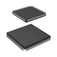
R5S72030W200FP Renesas Electronics America, R5S72030W200FP Datasheet - Page 856

R5S72030W200FP
Manufacturer Part Number
R5S72030W200FP
Description
IC SUPERH MPU ROMLESS 240QFP
Manufacturer
Renesas Electronics America
Series
SuperH® SH7200r
Specifications of R5S72030W200FP
Core Processor
SH2A-FPU
Core Size
32-Bit
Speed
200MHz
Connectivity
CAN, I²C, SCI, SSI, SSU, USB
Peripherals
DMA, LCD, POR, PWM, WDT
Number Of I /o
82
Program Memory Type
ROMless
Ram Size
80K x 8
Voltage - Supply (vcc/vdd)
1.1 V ~ 3.6 V
Data Converters
A/D 8x10b; D/A 2x8b
Oscillator Type
Internal
Operating Temperature
-20°C ~ 85°C
Package / Case
240-QFP
For Use With
R0K572030S000BE - KIT DEV FOR SH7203HS0005KCU11H - EMULATOR E10A-USB H8S(X),SH2(A)
Lead Free Status / RoHS Status
Contains lead / RoHS non-compliant
Eeprom Size
-
Program Memory Size
-
Available stocks
Company
Part Number
Manufacturer
Quantity
Price
Company:
Part Number:
R5S72030W200FP
Manufacturer:
SAMSUNG
Quantity:
1 001
Company:
Part Number:
R5S72030W200FP
Manufacturer:
Renesas Electronics America
Quantity:
10 000
- Current page: 856 of 1686
- Download datasheet (10Mb)
Section 16 Synchronous Serial Communication Unit (SSU)
(2)
Figure 16.13 shows an example of transmission operation, and figure 16.14 shows a flowchart
example of data transmission. When transmitting data in clock synchronous communication mode,
the SSU operates as shown below.
In master mode, the SSU outputs a transfer clock and data. In slave mode, when a transfer clock is
input to the SSCK pin, the SSU outputs data in synchronization with the transfer clock.
Writing transmit data to SSTDR after the TE bit is set to 1 clears the TDRE bit in SSSR to 0, and
the SSTDR contents are transferred to SSTRSR. After that, the SSU sets the TDRE bit to 1 and
starts transmission. At this time, if the TIE bit in SSER is set to 1, a transmit-data-empty SSTXI
interrupt is generated.
When 1-frame data has been transferred with TDRE = 0, the SSTDR contents are transferred to
SSTRSR to start the next frame transmission. When the 8th bit of transmit data has been
transferred with TDRE = 1, the TEND bit in SSSR is set to 1 and the state is retained. At this time,
if the TEIE bit in SSER is set to 1, a transmit-end SSTXI interrupt is generated.
While the ORER bit in SSSR is set to 1, transmission is not performed. Check that the ORER bit
is cleared to 0 before transmission.
Rev. 3.00 Sep. 28, 2009 Page 824 of 1650
REJ09B0313-0300
User operation
LSI operation
Data Transmission
SSCK
TDRE
TEND
SSO
Data written
to SSTDR
SSTXI interrupt
generated
Figure 16.13 Example of Transmission Operation
(Clock Synchronous Communication Mode)
Bit 0
Data written
to SSTDR
Bit 1
1 frame
Bit 7
SSTXI interrupt
generated
Bit 0
Bit 1
1 frame
SSTXI interrupt
generated
Bit 7
Related parts for R5S72030W200FP
Image
Part Number
Description
Manufacturer
Datasheet
Request
R

Part Number:
Description:
KIT STARTER FOR M16C/29
Manufacturer:
Renesas Electronics America
Datasheet:

Part Number:
Description:
KIT STARTER FOR R8C/2D
Manufacturer:
Renesas Electronics America
Datasheet:

Part Number:
Description:
R0K33062P STARTER KIT
Manufacturer:
Renesas Electronics America
Datasheet:

Part Number:
Description:
KIT STARTER FOR R8C/23 E8A
Manufacturer:
Renesas Electronics America
Datasheet:

Part Number:
Description:
KIT STARTER FOR R8C/25
Manufacturer:
Renesas Electronics America
Datasheet:

Part Number:
Description:
KIT STARTER H8S2456 SHARPE DSPLY
Manufacturer:
Renesas Electronics America
Datasheet:

Part Number:
Description:
KIT STARTER FOR R8C38C
Manufacturer:
Renesas Electronics America
Datasheet:

Part Number:
Description:
KIT STARTER FOR R8C35C
Manufacturer:
Renesas Electronics America
Datasheet:

Part Number:
Description:
KIT STARTER FOR R8CL3AC+LCD APPS
Manufacturer:
Renesas Electronics America
Datasheet:

Part Number:
Description:
KIT STARTER FOR RX610
Manufacturer:
Renesas Electronics America
Datasheet:

Part Number:
Description:
KIT STARTER FOR R32C/118
Manufacturer:
Renesas Electronics America
Datasheet:

Part Number:
Description:
KIT DEV RSK-R8C/26-29
Manufacturer:
Renesas Electronics America
Datasheet:

Part Number:
Description:
KIT STARTER FOR SH7124
Manufacturer:
Renesas Electronics America
Datasheet:

Part Number:
Description:
KIT STARTER FOR H8SX/1622
Manufacturer:
Renesas Electronics America
Datasheet:

Part Number:
Description:
KIT DEV FOR SH7203
Manufacturer:
Renesas Electronics America
Datasheet:


