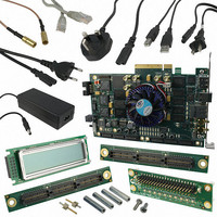
DK-DEV-4SGX230N Altera, DK-DEV-4SGX230N Datasheet - Page 868

DK-DEV-4SGX230N
Manufacturer Part Number
DK-DEV-4SGX230N
Description
KIT DEVELOPMENT STRATIX IV
Manufacturer
Altera
Series
Stratix® IVr
Type
FPGAr
Datasheets
1.EP4SGX110DF29C3N.pdf
(80 pages)
2.EP4SGX110DF29C3N.pdf
(1154 pages)
3.DK-DEV-4SGX230N.pdf
(2 pages)
4.DK-DEV-4SGX530N.pdf
(57 pages)
Specifications of DK-DEV-4SGX230N
Contents
Development Board, Universal Power Supply, Cables and Software
Silicon Manufacturer
Altera
Core Architecture
FPGA
Core Sub-architecture
Stratix
Silicon Core Number
EP4S
Silicon Family Name
Stratix IV GX
Rohs Compliant
Yes
For Use With/related Products
EP4SGX230K
Lead Free Status / RoHS Status
Lead free / RoHS Compliant
Other names
544-2594
Available stocks
Company
Part Number
Manufacturer
Quantity
Price
Company:
Part Number:
DK-DEV-4SGX230N
Manufacturer:
Altera
Quantity:
135
- EP4SGX110DF29C3N PDF datasheet
- EP4SGX110DF29C3N PDF datasheet #2
- DK-DEV-4SGX230N PDF datasheet #3
- DK-DEV-4SGX530N PDF datasheet #4
- Current page: 868 of 1154
- Download datasheet (32Mb)
5–22
Stratix IV Device Handbook Volume 2: Transceivers
1
1
1
A .mif is generated for every ALTGX instance defined in the top-level RTL file.
The Quartus II software creates the .mif under the <Project_DIR>/reconfig_mif folder.
The file name is based on the ALTGX instance name (<instance name>.mif); for
example, basic_gxb.mif. One design can have multiple .mifs (there is no limit) and
you can use one .mif to reconfigure multiple channels.
To generate a .mif, create a top-level design and connect the clock inputs in the
RTL/schematic. Specifically, for the transceiver clock inputs pll_inclk_cruclk.
If you do not specify pins for tx_dataout and rx_datain for the transceiver channel,
the Quartus II software selects a channel and generates a .mif for that channel.
However, the .mif can still be used for any transceiver channel.
You can generate multiple .mifs in the following two ways:
Method 1:
1. Compile the design created and generate the first .mif.
2. Update the ALTGX instance with the alternate configuration.
3. Compile the design to get the second .mif.
If you have to generate .mifs for many configurations, Method 1 takes more time to
complete.
Method 2:
1. In the top-level design, instantiate all the different configurations of the ALTGX
2. Connect the appropriate clock inputs of all the ALTGX instantiations.
3. Generate the .mif. The .mifs are generated for all the ALTGX configurations.
This method requires special attention when generating the .mif. Refer to the
following:
.mif-Based Design Flow
The .mif-based design flow involves writing the contents of the .mif to the transceiver
channel or CMU PLL.
instantiation for which the .mif is required.
■
■
■
The different ALTGX instantiations must have the appropriate logical
reference clock index option values.
The clock inputs for each instance must be connected to the appropriate clock
source.
When you generate the .mif, use the proper naming convention for the files so
you know the configuration supported by the .mif.
Chapter 5: Dynamic Reconfiguration in Stratix IV Devices
Dynamic Reconfiguration Modes Implementation
February 2011 Altera Corporation
Related parts for DK-DEV-4SGX230N
Image
Part Number
Description
Manufacturer
Datasheet
Request
R

Part Number:
Description:
KIT DEV ARRIA II GX FPGA 2AGX125
Manufacturer:
Altera
Datasheet:

Part Number:
Description:
KIT DEV CYCLONE III LS EP3CLS200
Manufacturer:
Altera
Datasheet:

Part Number:
Description:
KIT DEV STRATIX IV FPGA 4SE530
Manufacturer:
Altera
Datasheet:

Part Number:
Description:
KIT DEV FPGA 2AGX260 W/6.375G TX
Manufacturer:
Altera
Datasheet:

Part Number:
Description:
KIT DEV MAX V 5M570Z
Manufacturer:
Altera
Datasheet:

Part Number:
Description:
KIT DEV STRATIX V FPGA 5SGXEA7
Manufacturer:
Altera
Datasheet:

Part Number:
Description:
KIT DEVELOPMENT STRATIX III
Manufacturer:
Altera
Datasheet:

Part Number:
Description:
KIT DEV ARRIA GX 1AGX60N
Manufacturer:
Altera
Datasheet:

Part Number:
Description:
KIT STARTER CYCLONE IV GX
Manufacturer:
Altera
Datasheet:

Part Number:
Description:
KIT DEVELOPMENT STRATIX IV
Manufacturer:
Altera
Datasheet:

Part Number:
Description:
CPLD, EP610 Family, ECMOS Process, 300 Gates, 16 Macro Cells, 16 Reg., 16 User I/Os, 5V Supply, 35 Speed Grade, 24DIP
Manufacturer:
Altera Corporation
Datasheet:

Part Number:
Description:
CPLD, EP610 Family, ECMOS Process, 300 Gates, 16 Macro Cells, 16 Reg., 16 User I/Os, 5V Supply, 15 Speed Grade, 24DIP
Manufacturer:
Altera Corporation
Datasheet:


