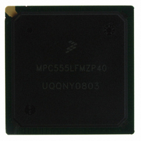
MPC555LFMZP40 Freescale Semiconductor, MPC555LFMZP40 Datasheet - Page 268

MPC555LFMZP40
Manufacturer Part Number
MPC555LFMZP40
Description
IC MCU 32BIT 40MHZ 272-BGA
Manufacturer
Freescale Semiconductor
Series
MPC5xxr
Datasheets
1.MPC555LFMZP40.pdf
(12 pages)
2.MPC555LFMZP40.pdf
(966 pages)
3.MPC555LFMZP40.pdf
(3 pages)
Specifications of MPC555LFMZP40
Core Processor
PowerPC
Core Size
32-Bit
Speed
40MHz
Connectivity
CAN, EBI/EMI, SCI, SPI, UART/USART
Peripherals
POR, PWM, WDT
Number Of I /o
101
Program Memory Size
448KB (448K x 8)
Program Memory Type
FLASH
Ram Size
26K x 8
Voltage - Supply (vcc/vdd)
2.5 V ~ 2.7 V
Data Converters
A/D 32x10b
Oscillator Type
External
Operating Temperature
-40°C ~ 125°C
Package / Case
272-PBGA
Controller Family/series
POWER 5xx
Ram Memory Size
26KB
Cpu Speed
63MIPS
Embedded Interface Type
QSPI, SCI, TouCAN
Operating Temperature Range
-40°C To +125°C
No. Of Pins
272
Rohs Compliant
No
Processor Series
MPC5xx
Core
PowerPC
Data Bus Width
32 bit
Data Ram Size
26 KB
Interface Type
CAN, QSPI, SCI
Maximum Clock Frequency
40 MHz
Number Of Programmable I/os
101
Operating Supply Voltage
3.3 V to 5 V
Maximum Operating Temperature
+ 125 C
Mounting Style
SMD/SMT
Development Tools By Supplier
MPC555CMEE
Minimum Operating Temperature
- 85 C
On-chip Adc
10 bit, 32 Channel
Cpu Family
MPC55xx
Device Core
PowerPC
Device Core Size
32b
Frequency (max)
40MHz
Total Internal Ram Size
32KB
# I/os (max)
101
Operating Supply Voltage (typ)
5V
Instruction Set Architecture
RISC
Operating Temp Range
-40C to 85C
Operating Temperature Classification
Industrial
Mounting
Surface Mount
Pin Count
272
Package Type
BGA
For Use With
MPC555CMEE - KIT EVAL FOR MPC555
Lead Free Status / RoHS Status
Contains lead / RoHS non-compliant
Eeprom Size
-
Lead Free Status / Rohs Status
No
Available stocks
Company
Part Number
Manufacturer
Quantity
Price
Company:
Part Number:
MPC555LFMZP40
Manufacturer:
MOTOLOLA
Quantity:
853
Company:
Part Number:
MPC555LFMZP40
Manufacturer:
Freescale Semiconductor
Quantity:
10 000
Company:
Part Number:
MPC555LFMZP40R2
Manufacturer:
Freescale Semiconductor
Quantity:
10 000
- Current page: 268 of 966
- Download datasheet (15Mb)
MPC555
USER’S MANUAL
GCLK2. When DFNH = 0, GCLK2_50 has a 50% duty cycle. With other values of
DFNH or DFNL, the duty cycle is less than 50%. Refer to
simultaneously with GCLK1. When the MPC555 / MPC556 is not in gear mode, the
falling edge of GCLK1_50 occurs in the middle of the high phase of GCLK2_50. EBDF
determines the division factor between GCLK1/GCLK2 and GCLK1_50/GCLK2_50.
During power-on reset, the MOCCK1, MODCK2, and MODCK3 pins determine the
clock source for the PLL and the clock drivers. These pins are latched on the positive
edge of PORESET. Their values must be stable as long as this line is asserted. The
configuration modes are shown in
the SPLL (OSCM or EXTCLK). MODCK1, MODCK2, and MODCK3 together deter-
mine the multiplication factor at reset and the functionality of limp mode.
If the configuration of PITRTCLK and TMBCLK and the SPLL multiplication factor is to
remain unchanged in power-down low-power mode, the MODCK signals should not
be sampled at wake-up from this mode. In this case the PORESET pin should remain
negated and HRESET should be asserted during the power supply wake-up stage.
When MODCK1 is cleared, the output of the main oscillator (OSCM) is selected as the
input to the SPLL. When MODCK1 is asserted, the external clock input (EXTCLK) is
selected as the input to the SPLL. In all cases, the system clock frequency (freq
can be reduced by the DFNH[0:2] bits in the SCCR. Note that freq
when the DFNH bits are cleared.
The TBS bit in the SCCR selects the time base clock to be either the SPLL input clock
or GCLK2. When the backup clock is functioning as the system clock, the backup clock
is automatically selected as the time base clock source.
The PITRTCLK frequency and source are specified by the RTDIV and RTSEL bits in
the SCCR. When the backup clock is functioning as the system clock, the backup
clock is automatically selected as the time base clock source.
When the PORESET pin is negated (driven to a high value), the MODCK1, MODCK2,
and MODCK3 values are not affected. They remain the same as they were defined
during the most recent power-on reset.
Table 8-1
serted).
/
MPC556
shows the clock configuration modes during power-on reset (PORESET as-
The MODCK[1:3] are shared functions with IRQ[5:7]. If IRQ[5:7] are
used as interrupts, the interrupt source should be removed during
PORESET to insure the MODCK pins are in the correct state on the
rising edge of PORESET.
Freescale Semiconductor, Inc.
For More Information On This Product,
CLOCKS AND POWER CONTROL
Go to: www.freescale.com
Rev. 15 October 2000
Table
NOTE
8-1. MODCK1 specifies the input source to
Figure
8-7. GCLK1_50 rises
gclk2(max)
MOTOROLA
occurs
gclk2
8-8
)
Related parts for MPC555LFMZP40
Image
Part Number
Description
Manufacturer
Datasheet
Request
R
Part Number:
Description:
Manufacturer:
Freescale Semiconductor, Inc
Datasheet:
Part Number:
Description:
Manufacturer:
Freescale Semiconductor, Inc
Datasheet:
Part Number:
Description:
Manufacturer:
Freescale Semiconductor, Inc
Datasheet:
Part Number:
Description:
Manufacturer:
Freescale Semiconductor, Inc
Datasheet:
Part Number:
Description:
Manufacturer:
Freescale Semiconductor, Inc
Datasheet:
Part Number:
Description:
Manufacturer:
Freescale Semiconductor, Inc
Datasheet:
Part Number:
Description:
Manufacturer:
Freescale Semiconductor, Inc
Datasheet:
Part Number:
Description:
Manufacturer:
Freescale Semiconductor, Inc
Datasheet:
Part Number:
Description:
Manufacturer:
Freescale Semiconductor, Inc
Datasheet:
Part Number:
Description:
Manufacturer:
Freescale Semiconductor, Inc
Datasheet:
Part Number:
Description:
Manufacturer:
Freescale Semiconductor, Inc
Datasheet:
Part Number:
Description:
Manufacturer:
Freescale Semiconductor, Inc
Datasheet:
Part Number:
Description:
Manufacturer:
Freescale Semiconductor, Inc
Datasheet:
Part Number:
Description:
Manufacturer:
Freescale Semiconductor, Inc
Datasheet:
Part Number:
Description:
Manufacturer:
Freescale Semiconductor, Inc
Datasheet:


