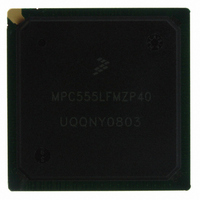
MPC555LFMZP40 Freescale Semiconductor, MPC555LFMZP40 Datasheet - Page 600

MPC555LFMZP40
Manufacturer Part Number
MPC555LFMZP40
Description
IC MCU 32BIT 40MHZ 272-BGA
Manufacturer
Freescale Semiconductor
Series
MPC5xxr
Datasheets
1.MPC555LFMZP40.pdf
(12 pages)
2.MPC555LFMZP40.pdf
(966 pages)
3.MPC555LFMZP40.pdf
(3 pages)
Specifications of MPC555LFMZP40
Core Processor
PowerPC
Core Size
32-Bit
Speed
40MHz
Connectivity
CAN, EBI/EMI, SCI, SPI, UART/USART
Peripherals
POR, PWM, WDT
Number Of I /o
101
Program Memory Size
448KB (448K x 8)
Program Memory Type
FLASH
Ram Size
26K x 8
Voltage - Supply (vcc/vdd)
2.5 V ~ 2.7 V
Data Converters
A/D 32x10b
Oscillator Type
External
Operating Temperature
-40°C ~ 125°C
Package / Case
272-PBGA
Controller Family/series
POWER 5xx
Ram Memory Size
26KB
Cpu Speed
63MIPS
Embedded Interface Type
QSPI, SCI, TouCAN
Operating Temperature Range
-40°C To +125°C
No. Of Pins
272
Rohs Compliant
No
Processor Series
MPC5xx
Core
PowerPC
Data Bus Width
32 bit
Data Ram Size
26 KB
Interface Type
CAN, QSPI, SCI
Maximum Clock Frequency
40 MHz
Number Of Programmable I/os
101
Operating Supply Voltage
3.3 V to 5 V
Maximum Operating Temperature
+ 125 C
Mounting Style
SMD/SMT
Development Tools By Supplier
MPC555CMEE
Minimum Operating Temperature
- 85 C
On-chip Adc
10 bit, 32 Channel
Cpu Family
MPC55xx
Device Core
PowerPC
Device Core Size
32b
Frequency (max)
40MHz
Total Internal Ram Size
32KB
# I/os (max)
101
Operating Supply Voltage (typ)
5V
Instruction Set Architecture
RISC
Operating Temp Range
-40C to 85C
Operating Temperature Classification
Industrial
Mounting
Surface Mount
Pin Count
272
Package Type
BGA
For Use With
MPC555CMEE - KIT EVAL FOR MPC555
Lead Free Status / RoHS Status
Contains lead / RoHS non-compliant
Eeprom Size
-
Lead Free Status / Rohs Status
No
Available stocks
Company
Part Number
Manufacturer
Quantity
Price
Company:
Part Number:
MPC555LFMZP40
Manufacturer:
MOTOLOLA
Quantity:
853
Company:
Part Number:
MPC555LFMZP40
Manufacturer:
Freescale Semiconductor
Quantity:
10 000
Company:
Part Number:
MPC555LFMZP40R2
Manufacturer:
Freescale Semiconductor
Quantity:
10 000
- Current page: 600 of 966
- Download datasheet (15Mb)
16.5.3 Auto Power Save Mode
MPC555
USER’S MANUAL
Auto power save mode enables normal operation with optimized power savings. Once
the auto power save (APS) bit in CANMCR is set, the TouCAN looks for a set of con-
ditions in which there is no need for the clocks to be running. If these conditions are
met, the TouCAN stops its clocks, thus saving power. The following conditions activate
auto power save mode.
While its clocks are stopped, if the TouCAN senses that any one of the aforementioned
conditions is no longer true, it restarts its clocks. The TouCAN then continues to mon-
itor these conditions and stops or restarts its clocks accordingly.
• To take the TouCAN out of low-power stop mode when the self wake mechanism
• The SELFWAKE bit should not be set after the TouCAN has already entered low-
• If both STOP and SELFWAKE are set and a recessive to dominant edge
• To prevent old frames from being sent when the TouCAN awakes from low-power
• If the TouCAN is in debug mode when the STOP bit is set, the TouCAN assumes
• Unlike other modules, the TouCAN does not come out of reset in low-power stop
• If the TouCAN is in low-power stop mode with the self wake mechanism engaged
• No Rx/Tx frame in progress
• No transfer of Rx/Tx frames to and from a serial message buffer, and no Tx frame
• No CPU access to the TouCAN module
• The TouCAN is not in debug mode, low-power stop mode, or the bus off state
/
for the TouCAN to set the STOPACK bit.
is enabled, write to CANMCR with both STOP and SELFWAKE clear, and then
wait for the TouCAN to clear the STOPACK bit.
power stop mode.
immediately occurs on the CAN bus, the TouCAN may never set the STOPACK
bit, and the STOP bit will be cleared.
stop mode via the self wake mechanism, disable all transmit sources, including
transmit buffers configured for remote request responses, before placing the Tou-
CAN in low-power stop mode.
that debug mode should be exited. As a result, it tries to synchronize with the CAN
bus, and only then does it await the conditions required for entry into low-power
stop mode.
mode. The basic TouCAN initialization procedure should be executed before
placing the module in low-power stop mode. (Refer to
tion.)
and is operating with a single IMB clock per time quantum, there can be extreme
cases in which TouCAN wake-up on recessive to dominant edge may not con-
form to the CAN protocol. TouCAN synchronization is shifted one time quantum
from the wake-up event. This shift lasts until the next recessive-to-dominant edge,
which resynchronizes the TouCAN to be in conformance with the CAN protocol.
The same holds true when the TouCAN is in auto power save mode and awakens
on a recessive to dominant edge.
awaiting transmission in any message buffer
MPC556
Freescale Semiconductor, Inc.
For More Information On This Product,
CAN 2.0B CONTROLLER MODULE
Go to: www.freescale.com
Rev. 15 October 2000
16.4.2 TouCAN Initializa-
MOTOROLA
16-18
Related parts for MPC555LFMZP40
Image
Part Number
Description
Manufacturer
Datasheet
Request
R
Part Number:
Description:
Manufacturer:
Freescale Semiconductor, Inc
Datasheet:
Part Number:
Description:
Manufacturer:
Freescale Semiconductor, Inc
Datasheet:
Part Number:
Description:
Manufacturer:
Freescale Semiconductor, Inc
Datasheet:
Part Number:
Description:
Manufacturer:
Freescale Semiconductor, Inc
Datasheet:
Part Number:
Description:
Manufacturer:
Freescale Semiconductor, Inc
Datasheet:
Part Number:
Description:
Manufacturer:
Freescale Semiconductor, Inc
Datasheet:
Part Number:
Description:
Manufacturer:
Freescale Semiconductor, Inc
Datasheet:
Part Number:
Description:
Manufacturer:
Freescale Semiconductor, Inc
Datasheet:
Part Number:
Description:
Manufacturer:
Freescale Semiconductor, Inc
Datasheet:
Part Number:
Description:
Manufacturer:
Freescale Semiconductor, Inc
Datasheet:
Part Number:
Description:
Manufacturer:
Freescale Semiconductor, Inc
Datasheet:
Part Number:
Description:
Manufacturer:
Freescale Semiconductor, Inc
Datasheet:
Part Number:
Description:
Manufacturer:
Freescale Semiconductor, Inc
Datasheet:
Part Number:
Description:
Manufacturer:
Freescale Semiconductor, Inc
Datasheet:
Part Number:
Description:
Manufacturer:
Freescale Semiconductor, Inc
Datasheet:


