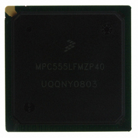
MPC555LFMZP40 Freescale Semiconductor, MPC555LFMZP40 Datasheet - Page 601

MPC555LFMZP40
Manufacturer Part Number
MPC555LFMZP40
Description
IC MCU 32BIT 40MHZ 272-BGA
Manufacturer
Freescale Semiconductor
Series
MPC5xxr
Datasheets
1.MPC555LFMZP40.pdf
(12 pages)
2.MPC555LFMZP40.pdf
(966 pages)
3.MPC555LFMZP40.pdf
(3 pages)
Specifications of MPC555LFMZP40
Core Processor
PowerPC
Core Size
32-Bit
Speed
40MHz
Connectivity
CAN, EBI/EMI, SCI, SPI, UART/USART
Peripherals
POR, PWM, WDT
Number Of I /o
101
Program Memory Size
448KB (448K x 8)
Program Memory Type
FLASH
Ram Size
26K x 8
Voltage - Supply (vcc/vdd)
2.5 V ~ 2.7 V
Data Converters
A/D 32x10b
Oscillator Type
External
Operating Temperature
-40°C ~ 125°C
Package / Case
272-PBGA
Controller Family/series
POWER 5xx
Ram Memory Size
26KB
Cpu Speed
63MIPS
Embedded Interface Type
QSPI, SCI, TouCAN
Operating Temperature Range
-40°C To +125°C
No. Of Pins
272
Rohs Compliant
No
Processor Series
MPC5xx
Core
PowerPC
Data Bus Width
32 bit
Data Ram Size
26 KB
Interface Type
CAN, QSPI, SCI
Maximum Clock Frequency
40 MHz
Number Of Programmable I/os
101
Operating Supply Voltage
3.3 V to 5 V
Maximum Operating Temperature
+ 125 C
Mounting Style
SMD/SMT
Development Tools By Supplier
MPC555CMEE
Minimum Operating Temperature
- 85 C
On-chip Adc
10 bit, 32 Channel
Cpu Family
MPC55xx
Device Core
PowerPC
Device Core Size
32b
Frequency (max)
40MHz
Total Internal Ram Size
32KB
# I/os (max)
101
Operating Supply Voltage (typ)
5V
Instruction Set Architecture
RISC
Operating Temp Range
-40C to 85C
Operating Temperature Classification
Industrial
Mounting
Surface Mount
Pin Count
272
Package Type
BGA
For Use With
MPC555CMEE - KIT EVAL FOR MPC555
Lead Free Status / RoHS Status
Contains lead / RoHS non-compliant
Eeprom Size
-
Lead Free Status / Rohs Status
No
Available stocks
Company
Part Number
Manufacturer
Quantity
Price
Company:
Part Number:
MPC555LFMZP40
Manufacturer:
MOTOLOLA
Quantity:
853
Company:
Part Number:
MPC555LFMZP40
Manufacturer:
Freescale Semiconductor
Quantity:
10 000
Company:
Part Number:
MPC555LFMZP40R2
Manufacturer:
Freescale Semiconductor
Quantity:
10 000
- Current page: 601 of 966
- Download datasheet (15Mb)
16.6 Interrupts
MPC555
USER’S MANUAL
The TouCAN can generate one interrupt level on the IMB. This level is programmed
into the priority level bits in the interrupt configuration register (CANICR). This value
determines which interrupt signal is driven onto the bus when an interrupt is requested.
Each one of the 16 message buffers can be an interrupt source, if its corresponding
IMASK bit is set. There is no distinction between transmit and receive interrupts for a
particular buffer. Each of the buffers is assigned a bit in the IFLAG register. An IFLAG
bit is set when the corresponding buffer completes a successful transmission/recep-
tion. An IFLAG bit is cleared when the CPU reads IFLAG while the associated bit is
set, and then writes it back as zero (and no new event of the same type occurs be-
tween the read and the write actions).
The other three interrupt sources (bus off, error and wake up) act in the same way, and
have flag bits located in the error and status register (ESTAT). The bus off and error
interrupt mask bits (BOFFMSK and ERRMSK) are located in CANCTRL0, and the
wake up interrupt mask bit (WAKEMSK) is located in the module configuration regis-
ter. Refer to
The TouCAN module is capable of generating one of the 32 possible interrupt levels
on the IMB3. The 32 interrupt levels are time multiplexed on the IMB3 IRQ[0:7] lines.
All interrupt sources place their asserted level on a time multiplexed bus during four
different time slots, with eight levels communicated per slot. The ILBS[0:1] signals in-
dicate which group of eight are being driven on the interrupt request lines.
The level that the TouCAN will drive onto IRQ[7:0] is programmed in the three interrupt
request level (IRL) bits located in the interrupt configuration register. The two ILBS bits
in the ICR register determine on which slot the TouCAN should drive its interrupt sig-
nal. Under the control of ILBS, each interrupt request level is driven during the time
multiplexed bus during one of four different time slots, with eight levels communicated
per time slot. No hardware priority is assigned to interrupts. Furthermore, if more than
one source on a module requests an interrupt at the same level, the system software
must assign a priority to each source requesting at that level.
interrupt levels on IRQ with ILBS.
/
MPC556
16.7 Programmer’s Model
Freescale Semiconductor, Inc.
For More Information On This Product,
CAN 2.0B CONTROLLER MODULE
Table 16-9 Interrupt Levels
Go to: www.freescale.com
ILBS[0:1]
Rev. 15 October 2000
00
01
10
11
for more information on these registers.
Levels
16:23
24:31
8:15
0:7
Figure 16-5
displays the
MOTOROLA
16-19
Related parts for MPC555LFMZP40
Image
Part Number
Description
Manufacturer
Datasheet
Request
R
Part Number:
Description:
Manufacturer:
Freescale Semiconductor, Inc
Datasheet:
Part Number:
Description:
Manufacturer:
Freescale Semiconductor, Inc
Datasheet:
Part Number:
Description:
Manufacturer:
Freescale Semiconductor, Inc
Datasheet:
Part Number:
Description:
Manufacturer:
Freescale Semiconductor, Inc
Datasheet:
Part Number:
Description:
Manufacturer:
Freescale Semiconductor, Inc
Datasheet:
Part Number:
Description:
Manufacturer:
Freescale Semiconductor, Inc
Datasheet:
Part Number:
Description:
Manufacturer:
Freescale Semiconductor, Inc
Datasheet:
Part Number:
Description:
Manufacturer:
Freescale Semiconductor, Inc
Datasheet:
Part Number:
Description:
Manufacturer:
Freescale Semiconductor, Inc
Datasheet:
Part Number:
Description:
Manufacturer:
Freescale Semiconductor, Inc
Datasheet:
Part Number:
Description:
Manufacturer:
Freescale Semiconductor, Inc
Datasheet:
Part Number:
Description:
Manufacturer:
Freescale Semiconductor, Inc
Datasheet:
Part Number:
Description:
Manufacturer:
Freescale Semiconductor, Inc
Datasheet:
Part Number:
Description:
Manufacturer:
Freescale Semiconductor, Inc
Datasheet:
Part Number:
Description:
Manufacturer:
Freescale Semiconductor, Inc
Datasheet:


