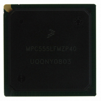
MPC555LFMZP40 Freescale Semiconductor, MPC555LFMZP40 Datasheet - Page 739

MPC555LFMZP40
Manufacturer Part Number
MPC555LFMZP40
Description
IC MCU 32BIT 40MHZ 272-BGA
Manufacturer
Freescale Semiconductor
Series
MPC5xxr
Datasheets
1.MPC555LFMZP40.pdf
(12 pages)
2.MPC555LFMZP40.pdf
(966 pages)
3.MPC555LFMZP40.pdf
(3 pages)
Specifications of MPC555LFMZP40
Core Processor
PowerPC
Core Size
32-Bit
Speed
40MHz
Connectivity
CAN, EBI/EMI, SCI, SPI, UART/USART
Peripherals
POR, PWM, WDT
Number Of I /o
101
Program Memory Size
448KB (448K x 8)
Program Memory Type
FLASH
Ram Size
26K x 8
Voltage - Supply (vcc/vdd)
2.5 V ~ 2.7 V
Data Converters
A/D 32x10b
Oscillator Type
External
Operating Temperature
-40°C ~ 125°C
Package / Case
272-PBGA
Controller Family/series
POWER 5xx
Ram Memory Size
26KB
Cpu Speed
63MIPS
Embedded Interface Type
QSPI, SCI, TouCAN
Operating Temperature Range
-40°C To +125°C
No. Of Pins
272
Rohs Compliant
No
Processor Series
MPC5xx
Core
PowerPC
Data Bus Width
32 bit
Data Ram Size
26 KB
Interface Type
CAN, QSPI, SCI
Maximum Clock Frequency
40 MHz
Number Of Programmable I/os
101
Operating Supply Voltage
3.3 V to 5 V
Maximum Operating Temperature
+ 125 C
Mounting Style
SMD/SMT
Development Tools By Supplier
MPC555CMEE
Minimum Operating Temperature
- 85 C
On-chip Adc
10 bit, 32 Channel
Cpu Family
MPC55xx
Device Core
PowerPC
Device Core Size
32b
Frequency (max)
40MHz
Total Internal Ram Size
32KB
# I/os (max)
101
Operating Supply Voltage (typ)
5V
Instruction Set Architecture
RISC
Operating Temp Range
-40C to 85C
Operating Temperature Classification
Industrial
Mounting
Surface Mount
Pin Count
272
Package Type
BGA
For Use With
MPC555CMEE - KIT EVAL FOR MPC555
Lead Free Status / RoHS Status
Contains lead / RoHS non-compliant
Eeprom Size
-
Lead Free Status / Rohs Status
No
Available stocks
Company
Part Number
Manufacturer
Quantity
Price
Company:
Part Number:
MPC555LFMZP40
Manufacturer:
MOTOLOLA
Quantity:
853
Company:
Part Number:
MPC555LFMZP40
Manufacturer:
Freescale Semiconductor
Quantity:
10 000
Company:
Part Number:
MPC555LFMZP40R2
Manufacturer:
Freescale Semiconductor
Quantity:
10 000
- Current page: 739 of 966
- Download datasheet (15Mb)
21.6 Software Monitor Debugger Support
21.6.1 Freeze Indication
21.7 Development Support Registers
MPC555
USER’S MANUAL
The sequence of the instructions used in the “fast download procedure” is the one il-
lustrated in
nitely until the “end download procedure” command is issued to the debug port.
Note that, the internal general purpose register 31 is used for temporary storage data
value. Before beginning the “fast download procedure” by the “start download proce-
dure command”, The value of the first memory block address, – 4, must be written to
the general purpose register 30.
To end a download procedure, an “end download procedure” command should be is-
sued to the debug port, and then, additional DATA transaction should be sent by the
development tool. This data word will NOT be placed into the system memory, but it is
needed to stop the procedure gracefully.
When in debug mode disable, a software monitor debugger can make use of all of the
development support features defined in the CPU. When debug mode is disabled all
events result in regular interrupt handling, i.e. the processor resumes execution in the
corresponding interrupt handler. The exception cause register (ECR) and the debug
enable register (DER) only influence the assertion and negation of the freeze signal.
The internal freeze signal is connected to all relevant internal modules. These modules
can be programmed to stop all operations in response to the assertion of the freeze
signal. In order to enable a software monitor debugger to broadcast the fact that the
debug software is now executed, it is possible to assert and negate the internal freeze
signal also when debug mode is disabled.
The assertion and negation of the freeze signal when in debug mode disable is con-
trolled by the exception cause register (ECR) and the debug enable register (DER) as
described in
program the relevant bits in the debug enable register (DER). In order to negate the
freeze line the software needs to read the exception cause register (ECR) in order to
clear it and perform an rfi instruction.
If the exception cause register (ECR) is not cleared before the rfi is performed the
freeze signal is not negated. Therefore it is possible to nest inside a software monitor
debugger without affecting the value of the freeze line although rfi may be performed
a few times. Only before the last rfi the software needs to clear the exception cause
register (ECR).
The above mechanism enables the software to accurately control the assertion and
the negation of the freeze signal.
Table 21-14
cessed with the mtspr and mfspr instructions.
/
MPC556
Figure 21-11
Figure
lists the registers used for development support. The registers are ac-
Freescale Semiconductor, Inc.
21-6. In order to assert the freeze signal the software needs to
For More Information On This Product,
with RX = r31 and RY = r30. This sequence is repeated infi-
DEVELOPMENT SUPPORT
Go to: www.freescale.com
Rev. 15 October 2000
MOTOROLA
21-43
Related parts for MPC555LFMZP40
Image
Part Number
Description
Manufacturer
Datasheet
Request
R
Part Number:
Description:
Manufacturer:
Freescale Semiconductor, Inc
Datasheet:
Part Number:
Description:
Manufacturer:
Freescale Semiconductor, Inc
Datasheet:
Part Number:
Description:
Manufacturer:
Freescale Semiconductor, Inc
Datasheet:
Part Number:
Description:
Manufacturer:
Freescale Semiconductor, Inc
Datasheet:
Part Number:
Description:
Manufacturer:
Freescale Semiconductor, Inc
Datasheet:
Part Number:
Description:
Manufacturer:
Freescale Semiconductor, Inc
Datasheet:
Part Number:
Description:
Manufacturer:
Freescale Semiconductor, Inc
Datasheet:
Part Number:
Description:
Manufacturer:
Freescale Semiconductor, Inc
Datasheet:
Part Number:
Description:
Manufacturer:
Freescale Semiconductor, Inc
Datasheet:
Part Number:
Description:
Manufacturer:
Freescale Semiconductor, Inc
Datasheet:
Part Number:
Description:
Manufacturer:
Freescale Semiconductor, Inc
Datasheet:
Part Number:
Description:
Manufacturer:
Freescale Semiconductor, Inc
Datasheet:
Part Number:
Description:
Manufacturer:
Freescale Semiconductor, Inc
Datasheet:
Part Number:
Description:
Manufacturer:
Freescale Semiconductor, Inc
Datasheet:
Part Number:
Description:
Manufacturer:
Freescale Semiconductor, Inc
Datasheet:


