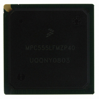
MPC555LFMZP40 Freescale Semiconductor, MPC555LFMZP40 Datasheet - Page 456

MPC555LFMZP40
Manufacturer Part Number
MPC555LFMZP40
Description
IC MCU 32BIT 40MHZ 272-BGA
Manufacturer
Freescale Semiconductor
Series
MPC5xxr
Datasheets
1.MPC555LFMZP40.pdf
(12 pages)
2.MPC555LFMZP40.pdf
(966 pages)
3.MPC555LFMZP40.pdf
(3 pages)
Specifications of MPC555LFMZP40
Core Processor
PowerPC
Core Size
32-Bit
Speed
40MHz
Connectivity
CAN, EBI/EMI, SCI, SPI, UART/USART
Peripherals
POR, PWM, WDT
Number Of I /o
101
Program Memory Size
448KB (448K x 8)
Program Memory Type
FLASH
Ram Size
26K x 8
Voltage - Supply (vcc/vdd)
2.5 V ~ 2.7 V
Data Converters
A/D 32x10b
Oscillator Type
External
Operating Temperature
-40°C ~ 125°C
Package / Case
272-PBGA
Controller Family/series
POWER 5xx
Ram Memory Size
26KB
Cpu Speed
63MIPS
Embedded Interface Type
QSPI, SCI, TouCAN
Operating Temperature Range
-40°C To +125°C
No. Of Pins
272
Rohs Compliant
No
Processor Series
MPC5xx
Core
PowerPC
Data Bus Width
32 bit
Data Ram Size
26 KB
Interface Type
CAN, QSPI, SCI
Maximum Clock Frequency
40 MHz
Number Of Programmable I/os
101
Operating Supply Voltage
3.3 V to 5 V
Maximum Operating Temperature
+ 125 C
Mounting Style
SMD/SMT
Development Tools By Supplier
MPC555CMEE
Minimum Operating Temperature
- 85 C
On-chip Adc
10 bit, 32 Channel
Cpu Family
MPC55xx
Device Core
PowerPC
Device Core Size
32b
Frequency (max)
40MHz
Total Internal Ram Size
32KB
# I/os (max)
101
Operating Supply Voltage (typ)
5V
Instruction Set Architecture
RISC
Operating Temp Range
-40C to 85C
Operating Temperature Classification
Industrial
Mounting
Surface Mount
Pin Count
272
Package Type
BGA
For Use With
MPC555CMEE - KIT EVAL FOR MPC555
Lead Free Status / RoHS Status
Contains lead / RoHS non-compliant
Eeprom Size
-
Lead Free Status / Rohs Status
No
Available stocks
Company
Part Number
Manufacturer
Quantity
Price
Company:
Part Number:
MPC555LFMZP40
Manufacturer:
MOTOLOLA
Quantity:
853
Company:
Part Number:
MPC555LFMZP40
Manufacturer:
Freescale Semiconductor
Quantity:
10 000
Company:
Part Number:
MPC555LFMZP40R2
Manufacturer:
Freescale Semiconductor
Quantity:
10 000
- Current page: 456 of 966
- Download datasheet (15Mb)
MPC555
USER’S MANUAL
BQ2
00
63
Figure 13-12
To prepare the QADC64 for a scan sequence, the software writes to the CCW table to
specify the desired channel conversions. The software also establishes the criteria for
initiating the queue execution by programming the queue operating mode. The queue
operating mode determines what type of trigger event causes queue execution to be-
gin. “Trigger event” refers to any of the ways to cause the QADC64 to begin executing
the CCWs in a queue or sub-queue. An external trigger is only one of the possible trig-
ger events.
A scan sequence may be initiated by the following:
LSB
6
P
CONVERSION COMMAND WORD
CHAN = CHANNEL NUMBER AND END-OF-QUEUE CODE
BYP = BYPASS BUFFER AMPLIFIER
• A software command
IST = INPUT SAMPLE TIME
BYP
P = PAUSE AFTER CONVERSION UNTIL NEXT TRIGGER
7
/
END OF Queue 1
END OF Queue 2
MPC556 QUEUED ANALOG-TO-DIGITAL CONVERTER MODULE-64
BEGIN Queue 1
BEGIN Queue 2
(CCW) TABLE
10-BIT CONVERSION COMMAND
8
IST
9
WORD FORMAT
Figure 13-12 QADC64 Conversion Queue Operation
illustrates the operation of the queue structure.
10
11
Freescale Semiconductor, Inc.
CHAN
12
For More Information On This Product,
13
SAMPLE, HOLD, AND
CHANNEL SELECT,
A/D CONVERSION
14
Go to: www.freescale.com
Rev. 15 October 2000
15
MSB
S = SIGN BIT
MSB
MSB
MSB
0
0
0
0
S
1
1
1
0
RIGHT JUSTIFIED, UNSIGNED RESULT
LEFT JUSTIFIED, UNSIGNED RESULT
2
2
2
0
LEFT JUSTIFIED, SIGNED RESULT
10-BIT RESULT, READABLE IN
3
RESULT
3
3
0
RESULT
THREE 16-BIT FORMATS
4
4
RESULT WORD TABLE
4
0
5
5
5
0
6
6
6
7
7
7
8
8
8
9
9
9
RESULT
0
0
10
10
10
0
0
11 12 13 14
11 12 13 14
11 12 13 14
0
0
MOTOROLA
0
0
0
0
LSB
LSB
LSB
0
0
15
15
15
13-44
QADC64 C
00
63
Related parts for MPC555LFMZP40
Image
Part Number
Description
Manufacturer
Datasheet
Request
R
Part Number:
Description:
Manufacturer:
Freescale Semiconductor, Inc
Datasheet:
Part Number:
Description:
Manufacturer:
Freescale Semiconductor, Inc
Datasheet:
Part Number:
Description:
Manufacturer:
Freescale Semiconductor, Inc
Datasheet:
Part Number:
Description:
Manufacturer:
Freescale Semiconductor, Inc
Datasheet:
Part Number:
Description:
Manufacturer:
Freescale Semiconductor, Inc
Datasheet:
Part Number:
Description:
Manufacturer:
Freescale Semiconductor, Inc
Datasheet:
Part Number:
Description:
Manufacturer:
Freescale Semiconductor, Inc
Datasheet:
Part Number:
Description:
Manufacturer:
Freescale Semiconductor, Inc
Datasheet:
Part Number:
Description:
Manufacturer:
Freescale Semiconductor, Inc
Datasheet:
Part Number:
Description:
Manufacturer:
Freescale Semiconductor, Inc
Datasheet:
Part Number:
Description:
Manufacturer:
Freescale Semiconductor, Inc
Datasheet:
Part Number:
Description:
Manufacturer:
Freescale Semiconductor, Inc
Datasheet:
Part Number:
Description:
Manufacturer:
Freescale Semiconductor, Inc
Datasheet:
Part Number:
Description:
Manufacturer:
Freescale Semiconductor, Inc
Datasheet:
Part Number:
Description:
Manufacturer:
Freescale Semiconductor, Inc
Datasheet:


