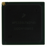
MPC555LFMZP40 Freescale Semiconductor, MPC555LFMZP40 Datasheet - Page 339

MPC555LFMZP40
Manufacturer Part Number
MPC555LFMZP40
Description
IC MCU 32BIT 40MHZ 272-BGA
Manufacturer
Freescale Semiconductor
Series
MPC5xxr
Datasheets
1.MPC555LFMZP40.pdf
(12 pages)
2.MPC555LFMZP40.pdf
(966 pages)
3.MPC555LFMZP40.pdf
(3 pages)
Specifications of MPC555LFMZP40
Core Processor
PowerPC
Core Size
32-Bit
Speed
40MHz
Connectivity
CAN, EBI/EMI, SCI, SPI, UART/USART
Peripherals
POR, PWM, WDT
Number Of I /o
101
Program Memory Size
448KB (448K x 8)
Program Memory Type
FLASH
Ram Size
26K x 8
Voltage - Supply (vcc/vdd)
2.5 V ~ 2.7 V
Data Converters
A/D 32x10b
Oscillator Type
External
Operating Temperature
-40°C ~ 125°C
Package / Case
272-PBGA
Controller Family/series
POWER 5xx
Ram Memory Size
26KB
Cpu Speed
63MIPS
Embedded Interface Type
QSPI, SCI, TouCAN
Operating Temperature Range
-40°C To +125°C
No. Of Pins
272
Rohs Compliant
No
Processor Series
MPC5xx
Core
PowerPC
Data Bus Width
32 bit
Data Ram Size
26 KB
Interface Type
CAN, QSPI, SCI
Maximum Clock Frequency
40 MHz
Number Of Programmable I/os
101
Operating Supply Voltage
3.3 V to 5 V
Maximum Operating Temperature
+ 125 C
Mounting Style
SMD/SMT
Development Tools By Supplier
MPC555CMEE
Minimum Operating Temperature
- 85 C
On-chip Adc
10 bit, 32 Channel
Cpu Family
MPC55xx
Device Core
PowerPC
Device Core Size
32b
Frequency (max)
40MHz
Total Internal Ram Size
32KB
# I/os (max)
101
Operating Supply Voltage (typ)
5V
Instruction Set Architecture
RISC
Operating Temp Range
-40C to 85C
Operating Temperature Classification
Industrial
Mounting
Surface Mount
Pin Count
272
Package Type
BGA
For Use With
MPC555CMEE - KIT EVAL FOR MPC555
Lead Free Status / RoHS Status
Contains lead / RoHS non-compliant
Eeprom Size
-
Lead Free Status / Rohs Status
No
Available stocks
Company
Part Number
Manufacturer
Quantity
Price
Company:
Part Number:
MPC555LFMZP40
Manufacturer:
MOTOLOLA
Quantity:
853
Company:
Part Number:
MPC555LFMZP40
Manufacturer:
Freescale Semiconductor
Quantity:
10 000
Company:
Part Number:
MPC555LFMZP40R2
Manufacturer:
Freescale Semiconductor
Quantity:
10 000
- Current page: 339 of 966
- Download datasheet (15Mb)
9.5.10 Bus Exception Control Cycles
9.5.10.1 Retrying a Bus Cycle
MPC555
USER’S MANUAL
The MPC555 / MPC556 bus architecture requires assertion of TA from an external de-
vice to signal that the bus cycle is complete. TA is not asserted in the following cases:
External circuitry can provide TEA when no device responds by asserting TA within an
appropriate period of time after the MPC555 / MPC556 initiates the bus cycle (it can
be the internal bus monitor). This allows the cycle to terminate and the processor to
enter exception-processing for the error condition (each one of the internal masters
causes an internal interrupt under this situation). To properly control termination of a
bus cycle for a bus error, TEA must be asserted at the same time or before TA is as-
serted. TEA should be negated before the second rising edge after it was sampled as
asserted to avoid the detection of an error for the next initiated bus cycle. TEA is an
open drain pin that allows the “wired-or” of any different sources of error generation.
When an external device asserts the RETRY signal during a bus cycle, the MPC555 /
MPC556 enters a sequence in which it terminates the current transaction, relinquishes
the ownership of the bus, and retries the cycle using the same address, address at-
tributes, and data (in the case of a write cycle).
Figure 9-31
is detected as a termination of a transfer. As seen in this figure, in the case when the
internal arbiter is enabled, the MPC555 / MPC556 negates BB and asserts BG in the
clock cycle following the retry detection. This allows any external master to gain bus
ownership. In the next clock cycle, a normal arbitration procedure occurs again. As
shown in the figure, the external master did not use the bus, so the MPC555 / MPC556
initiates a new transfer with the same address and attributes as before.
In
working with an external arbiter. In this case, in the clock cycle after the RETRY signal
is detected asserted, BR is negated together with BB. One clock cycle later, the normal
arbitration procedure occurs again.
Figure
• The external device does not respond
• Various other application-dependent errors occur
/
the bus interface should not perform the remote bus write-access or abort it if the
remote bus supports aborted cycles. In this case the failure of the stwcx instruc-
tion is reported to the RCPU.
MPC556
9-32, the same situation is shown except that the MPC555 / MPC556 is
illustrates the behavior of the MPC555 / MPC556 when the RETRY signal
Freescale Semiconductor, Inc.
For More Information On This Product,
EXTERNAL BUS INTERFACE
Go to: www.freescale.com
Rev. 15 October 2000
MOTOROLA
9-43
Related parts for MPC555LFMZP40
Image
Part Number
Description
Manufacturer
Datasheet
Request
R
Part Number:
Description:
Manufacturer:
Freescale Semiconductor, Inc
Datasheet:
Part Number:
Description:
Manufacturer:
Freescale Semiconductor, Inc
Datasheet:
Part Number:
Description:
Manufacturer:
Freescale Semiconductor, Inc
Datasheet:
Part Number:
Description:
Manufacturer:
Freescale Semiconductor, Inc
Datasheet:
Part Number:
Description:
Manufacturer:
Freescale Semiconductor, Inc
Datasheet:
Part Number:
Description:
Manufacturer:
Freescale Semiconductor, Inc
Datasheet:
Part Number:
Description:
Manufacturer:
Freescale Semiconductor, Inc
Datasheet:
Part Number:
Description:
Manufacturer:
Freescale Semiconductor, Inc
Datasheet:
Part Number:
Description:
Manufacturer:
Freescale Semiconductor, Inc
Datasheet:
Part Number:
Description:
Manufacturer:
Freescale Semiconductor, Inc
Datasheet:
Part Number:
Description:
Manufacturer:
Freescale Semiconductor, Inc
Datasheet:
Part Number:
Description:
Manufacturer:
Freescale Semiconductor, Inc
Datasheet:
Part Number:
Description:
Manufacturer:
Freescale Semiconductor, Inc
Datasheet:
Part Number:
Description:
Manufacturer:
Freescale Semiconductor, Inc
Datasheet:
Part Number:
Description:
Manufacturer:
Freescale Semiconductor, Inc
Datasheet:


