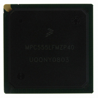
MPC555LFMZP40 Freescale Semiconductor, MPC555LFMZP40 Datasheet - Page 921

MPC555LFMZP40
Manufacturer Part Number
MPC555LFMZP40
Description
IC MCU 32BIT 40MHZ 272-BGA
Manufacturer
Freescale Semiconductor
Series
MPC5xxr
Datasheets
1.MPC555LFMZP40.pdf
(12 pages)
2.MPC555LFMZP40.pdf
(966 pages)
3.MPC555LFMZP40.pdf
(3 pages)
Specifications of MPC555LFMZP40
Core Processor
PowerPC
Core Size
32-Bit
Speed
40MHz
Connectivity
CAN, EBI/EMI, SCI, SPI, UART/USART
Peripherals
POR, PWM, WDT
Number Of I /o
101
Program Memory Size
448KB (448K x 8)
Program Memory Type
FLASH
Ram Size
26K x 8
Voltage - Supply (vcc/vdd)
2.5 V ~ 2.7 V
Data Converters
A/D 32x10b
Oscillator Type
External
Operating Temperature
-40°C ~ 125°C
Package / Case
272-PBGA
Controller Family/series
POWER 5xx
Ram Memory Size
26KB
Cpu Speed
63MIPS
Embedded Interface Type
QSPI, SCI, TouCAN
Operating Temperature Range
-40°C To +125°C
No. Of Pins
272
Rohs Compliant
No
Processor Series
MPC5xx
Core
PowerPC
Data Bus Width
32 bit
Data Ram Size
26 KB
Interface Type
CAN, QSPI, SCI
Maximum Clock Frequency
40 MHz
Number Of Programmable I/os
101
Operating Supply Voltage
3.3 V to 5 V
Maximum Operating Temperature
+ 125 C
Mounting Style
SMD/SMT
Development Tools By Supplier
MPC555CMEE
Minimum Operating Temperature
- 85 C
On-chip Adc
10 bit, 32 Channel
Cpu Family
MPC55xx
Device Core
PowerPC
Device Core Size
32b
Frequency (max)
40MHz
Total Internal Ram Size
32KB
# I/os (max)
101
Operating Supply Voltage (typ)
5V
Instruction Set Architecture
RISC
Operating Temp Range
-40C to 85C
Operating Temperature Classification
Industrial
Mounting
Surface Mount
Pin Count
272
Package Type
BGA
For Use With
MPC555CMEE - KIT EVAL FOR MPC555
Lead Free Status / RoHS Status
Contains lead / RoHS non-compliant
Eeprom Size
-
Lead Free Status / Rohs Status
No
Available stocks
Company
Part Number
Manufacturer
Quantity
Price
Company:
Part Number:
MPC555LFMZP40
Manufacturer:
MOTOLOLA
Quantity:
853
Company:
Part Number:
MPC555LFMZP40
Manufacturer:
Freescale Semiconductor
Quantity:
10 000
Company:
Part Number:
MPC555LFMZP40R2
Manufacturer:
Freescale Semiconductor
Quantity:
10 000
- Current page: 921 of 966
- Download datasheet (15Mb)
G.14 Reset Timing
MPC555 / MPC556
USER’S MANUAL
49a
55a
NOTES:
43
44
45
46
47
48
49
50
51
52
53
54
55
1. Weak pullups and pulldowns used for Reset timing will comply with the 130-µA mode select current outlined in
2. HRESET, SRESET and PORESET have a glitch detector to ensure that spikes less than 20 ns are rejected. The
Table
tion, is to connect RSTCONF/TEXP to SRESET. The maximum rise time of HRESET should be less than six
clock cycles.
internal HRESET, SRESET and PORESET will assert only if these signals are asserted for more than 100 ns.
CLKOUT to HRESET High Impedance
CLKOUT to SRESET High Impedance
RSTCONF Pulse Width
Configuration Data to HRESET Rising
Edge Setup Time
Configuration Data to RSTCONF
Rising Edge Set Up Time
Configuration Data Hold Time After
RSTCONF Negation
Configuration Data Hold Time After
HRESET Negation
RSTCONF Hold Time After HRESET
Negation
HRESET and RSTCONF Asserted to
Data Out Drive
RSTCONF Negated to Data Out High
Impedance.
CLKOUT of Last Rising Edge Before
Chip Tristates HRESET to Data Out
High Impedance.
DSDI, DSCK Set Up
DSDI, DSCK hold time
SRESET Negated to CLKOUT Rising
Edge for DSDI and DSCK Sample
HRESET, SRESET, PORESET Pulse
Width
G-4.The simplest way to insure meeting this requirement in systems that require the use of the TEXP func-
2
1
Characteristic
Freescale Semiconductor, Inc.
For More Information On This Product,
ELECTRICAL CHARACTERISTICS
Table G-14 RESET Timing
Go to: www.freescale.com
Rev. 15 October 2000
(T
15*TC + TCC
15*TC + TCC
Expression
A
17*TC
= T
8*TC
3*TC
L
to T
H
)
Min
515
463
463
243
100
60
25
25
25
91
0
0
0
33MHz
Max
20
20
Min
425
382
382
200
100
50
25
25
25
75
0
0
0
40MHz
Max
20
20
MOTOROLA
Unit
ns
ns
ns
ns
ns
ns
ns
ns
ns
ns
ns
ns
ns
ns
ns
G-43
Related parts for MPC555LFMZP40
Image
Part Number
Description
Manufacturer
Datasheet
Request
R
Part Number:
Description:
Manufacturer:
Freescale Semiconductor, Inc
Datasheet:
Part Number:
Description:
Manufacturer:
Freescale Semiconductor, Inc
Datasheet:
Part Number:
Description:
Manufacturer:
Freescale Semiconductor, Inc
Datasheet:
Part Number:
Description:
Manufacturer:
Freescale Semiconductor, Inc
Datasheet:
Part Number:
Description:
Manufacturer:
Freescale Semiconductor, Inc
Datasheet:
Part Number:
Description:
Manufacturer:
Freescale Semiconductor, Inc
Datasheet:
Part Number:
Description:
Manufacturer:
Freescale Semiconductor, Inc
Datasheet:
Part Number:
Description:
Manufacturer:
Freescale Semiconductor, Inc
Datasheet:
Part Number:
Description:
Manufacturer:
Freescale Semiconductor, Inc
Datasheet:
Part Number:
Description:
Manufacturer:
Freescale Semiconductor, Inc
Datasheet:
Part Number:
Description:
Manufacturer:
Freescale Semiconductor, Inc
Datasheet:
Part Number:
Description:
Manufacturer:
Freescale Semiconductor, Inc
Datasheet:
Part Number:
Description:
Manufacturer:
Freescale Semiconductor, Inc
Datasheet:
Part Number:
Description:
Manufacturer:
Freescale Semiconductor, Inc
Datasheet:
Part Number:
Description:
Manufacturer:
Freescale Semiconductor, Inc
Datasheet:


