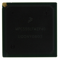
MPC555LFMZP40 Freescale Semiconductor, MPC555LFMZP40 Datasheet - Page 435

MPC555LFMZP40
Manufacturer Part Number
MPC555LFMZP40
Description
IC MCU 32BIT 40MHZ 272-BGA
Manufacturer
Freescale Semiconductor
Series
MPC5xxr
Datasheets
1.MPC555LFMZP40.pdf
(12 pages)
2.MPC555LFMZP40.pdf
(966 pages)
3.MPC555LFMZP40.pdf
(3 pages)
Specifications of MPC555LFMZP40
Core Processor
PowerPC
Core Size
32-Bit
Speed
40MHz
Connectivity
CAN, EBI/EMI, SCI, SPI, UART/USART
Peripherals
POR, PWM, WDT
Number Of I /o
101
Program Memory Size
448KB (448K x 8)
Program Memory Type
FLASH
Ram Size
26K x 8
Voltage - Supply (vcc/vdd)
2.5 V ~ 2.7 V
Data Converters
A/D 32x10b
Oscillator Type
External
Operating Temperature
-40°C ~ 125°C
Package / Case
272-PBGA
Controller Family/series
POWER 5xx
Ram Memory Size
26KB
Cpu Speed
63MIPS
Embedded Interface Type
QSPI, SCI, TouCAN
Operating Temperature Range
-40°C To +125°C
No. Of Pins
272
Rohs Compliant
No
Processor Series
MPC5xx
Core
PowerPC
Data Bus Width
32 bit
Data Ram Size
26 KB
Interface Type
CAN, QSPI, SCI
Maximum Clock Frequency
40 MHz
Number Of Programmable I/os
101
Operating Supply Voltage
3.3 V to 5 V
Maximum Operating Temperature
+ 125 C
Mounting Style
SMD/SMT
Development Tools By Supplier
MPC555CMEE
Minimum Operating Temperature
- 85 C
On-chip Adc
10 bit, 32 Channel
Cpu Family
MPC55xx
Device Core
PowerPC
Device Core Size
32b
Frequency (max)
40MHz
Total Internal Ram Size
32KB
# I/os (max)
101
Operating Supply Voltage (typ)
5V
Instruction Set Architecture
RISC
Operating Temp Range
-40C to 85C
Operating Temperature Classification
Industrial
Mounting
Surface Mount
Pin Count
272
Package Type
BGA
For Use With
MPC555CMEE - KIT EVAL FOR MPC555
Lead Free Status / RoHS Status
Contains lead / RoHS non-compliant
Eeprom Size
-
Lead Free Status / Rohs Status
No
Available stocks
Company
Part Number
Manufacturer
Quantity
Price
Company:
Part Number:
MPC555LFMZP40
Manufacturer:
MOTOLOLA
Quantity:
853
Company:
Part Number:
MPC555LFMZP40
Manufacturer:
Freescale Semiconductor
Quantity:
10 000
Company:
Part Number:
MPC555LFMZP40R2
Manufacturer:
Freescale Semiconductor
Quantity:
10 000
- Current page: 435 of 966
- Download datasheet (15Mb)
MPC555
USER’S MANUAL
The software initiated continuous-scan mode keeps the result registers updated more
frequently than any of the other queue operating modes. The software can always
read the result table to get the latest converted value for each channel. The channels
scanned are kept up-to-date by the QADC64 without software involvement. Software
can read a result value at any time.
The software initiated continuous-scan mode may be chosen for either queue, but is
normally used only with queue 2. When the software initiated continuous-scan mode
is chosen for queue 1, that queue operates continuously and queue 2, being lower in
priority, never gets executed. The short interval of time between a queue 1 completion
and the subsequent trigger event is not sufficient to allow queue 2 execution to begin.
The software initiated continuous-scan mode is a useful choice with queue 2 for con-
verting channels that do not need to be synchronized to anything, or for the slow-to-
change analog channels. Interrupts are normally not used with the software initiated
continuous-scan mode. Rather, the software reads the latest conversion result from
the result table at any time. Once initiated, software action is not needed to sustain
conversions of channel. Data read at different locations, however, may or may not be
coherent (that is, from the same queue scan sequence).
External Trigger Continuous-Scan Mode. The QADC64 provides external trigger
pins for both queues. When the external trigger software initiated continuous-scan
mode is selected, a transition on the associated external trigger pin initiates queue ex-
ecution. The polarity of the external trigger signal is programmable, so that the soft-
ware can choose to begin queue execution on the rising or falling edge. Each CCW is
read and the indicated conversions are performed until an end-of-queue condition is
encountered. When the next external trigger edge is detected, the queue execution
begins again automatically. Software initialization is not needed between trigger
events.
When a pause bit is encountered in external trigger continuous-scan mode, another
trigger event is required for queue execution to continue. Software involvement is not
needed to enable queue execution to continue from the paused state.
Some applications need to synchronize the sampling of analog channels to external
events. There are cases when it is not possible to use software initiation of the queue
scan sequence, since interrupt response times vary.
External Gated Continuous-Scan Mode. The QADC64 provides external gating for
queue 1 only. When external gated continuous-scan mode is selected, a transition on
the associated external trigger pin initiates queue execution. The polarity of the exter-
nal gated signal is fixed so a high level opens the gate and a low level closes the gate.
Once the gate is open, each CCW is read and the indicated conversions are per-
formed until the gate is closed. When the gate opens again, the queue execution au-
tomatically begins again from the beginning of the queue. Software initialization is not
needed between trigger events. If a pause in a CCW is encountered, the pause flag
will not set, and execution continues without pausing.
/
MPC556 QUEUED ANALOG-TO-DIGITAL CONVERTER MODULE-64
Freescale Semiconductor, Inc.
For More Information On This Product,
Go to: www.freescale.com
Rev. 15 October 2000
MOTOROLA
13-23
Related parts for MPC555LFMZP40
Image
Part Number
Description
Manufacturer
Datasheet
Request
R
Part Number:
Description:
Manufacturer:
Freescale Semiconductor, Inc
Datasheet:
Part Number:
Description:
Manufacturer:
Freescale Semiconductor, Inc
Datasheet:
Part Number:
Description:
Manufacturer:
Freescale Semiconductor, Inc
Datasheet:
Part Number:
Description:
Manufacturer:
Freescale Semiconductor, Inc
Datasheet:
Part Number:
Description:
Manufacturer:
Freescale Semiconductor, Inc
Datasheet:
Part Number:
Description:
Manufacturer:
Freescale Semiconductor, Inc
Datasheet:
Part Number:
Description:
Manufacturer:
Freescale Semiconductor, Inc
Datasheet:
Part Number:
Description:
Manufacturer:
Freescale Semiconductor, Inc
Datasheet:
Part Number:
Description:
Manufacturer:
Freescale Semiconductor, Inc
Datasheet:
Part Number:
Description:
Manufacturer:
Freescale Semiconductor, Inc
Datasheet:
Part Number:
Description:
Manufacturer:
Freescale Semiconductor, Inc
Datasheet:
Part Number:
Description:
Manufacturer:
Freescale Semiconductor, Inc
Datasheet:
Part Number:
Description:
Manufacturer:
Freescale Semiconductor, Inc
Datasheet:
Part Number:
Description:
Manufacturer:
Freescale Semiconductor, Inc
Datasheet:
Part Number:
Description:
Manufacturer:
Freescale Semiconductor, Inc
Datasheet:


