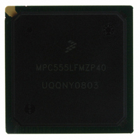
MPC555LFMZP40 Freescale Semiconductor, MPC555LFMZP40 Datasheet - Page 431

MPC555LFMZP40
Manufacturer Part Number
MPC555LFMZP40
Description
IC MCU 32BIT 40MHZ 272-BGA
Manufacturer
Freescale Semiconductor
Series
MPC5xxr
Datasheets
1.MPC555LFMZP40.pdf
(12 pages)
2.MPC555LFMZP40.pdf
(966 pages)
3.MPC555LFMZP40.pdf
(3 pages)
Specifications of MPC555LFMZP40
Core Processor
PowerPC
Core Size
32-Bit
Speed
40MHz
Connectivity
CAN, EBI/EMI, SCI, SPI, UART/USART
Peripherals
POR, PWM, WDT
Number Of I /o
101
Program Memory Size
448KB (448K x 8)
Program Memory Type
FLASH
Ram Size
26K x 8
Voltage - Supply (vcc/vdd)
2.5 V ~ 2.7 V
Data Converters
A/D 32x10b
Oscillator Type
External
Operating Temperature
-40°C ~ 125°C
Package / Case
272-PBGA
Controller Family/series
POWER 5xx
Ram Memory Size
26KB
Cpu Speed
63MIPS
Embedded Interface Type
QSPI, SCI, TouCAN
Operating Temperature Range
-40°C To +125°C
No. Of Pins
272
Rohs Compliant
No
Processor Series
MPC5xx
Core
PowerPC
Data Bus Width
32 bit
Data Ram Size
26 KB
Interface Type
CAN, QSPI, SCI
Maximum Clock Frequency
40 MHz
Number Of Programmable I/os
101
Operating Supply Voltage
3.3 V to 5 V
Maximum Operating Temperature
+ 125 C
Mounting Style
SMD/SMT
Development Tools By Supplier
MPC555CMEE
Minimum Operating Temperature
- 85 C
On-chip Adc
10 bit, 32 Channel
Cpu Family
MPC55xx
Device Core
PowerPC
Device Core Size
32b
Frequency (max)
40MHz
Total Internal Ram Size
32KB
# I/os (max)
101
Operating Supply Voltage (typ)
5V
Instruction Set Architecture
RISC
Operating Temp Range
-40C to 85C
Operating Temperature Classification
Industrial
Mounting
Surface Mount
Pin Count
272
Package Type
BGA
For Use With
MPC555CMEE - KIT EVAL FOR MPC555
Lead Free Status / RoHS Status
Contains lead / RoHS non-compliant
Eeprom Size
-
Lead Free Status / Rohs Status
No
Available stocks
Company
Part Number
Manufacturer
Quantity
Price
Company:
Part Number:
MPC555LFMZP40
Manufacturer:
MOTOLOLA
Quantity:
853
Company:
Part Number:
MPC555LFMZP40
Manufacturer:
Freescale Semiconductor
Quantity:
10 000
Company:
Part Number:
MPC555LFMZP40R2
Manufacturer:
Freescale Semiconductor
Quantity:
10 000
- Current page: 431 of 966
- Download datasheet (15Mb)
MPC555
USER’S MANUAL
In all single-scan queue operating modes, the software must also enable the queue to
begin execution by writing the single-scan enable bit to a one in the queue’s control
register. The single-scan enable bits, SSE1 and SSE2, are provided for queue 1 and
queue 2 respectively.
Until the single-scan enable bit is set, any trigger events for that queue are ignored.
The single-scan enable bit may be set to a one during the write cycle, which selects
the single-scan queue operating mode. The single-scan enable bit can be written as a
one or a zero, but is always read as a zero. The completion flag, completion interrupt,
or queue status are used to determine when the queue has completed.
After the single-scan enable bit is set, a trigger event causes the QADC64 to begin ex-
ecution with the first CCW in the queue. The single-scan enable bit remains set until
the queue is completed. After the queue reaches completion, the QADC64 resets the
single-scan enable bit to zero. If the single-scan enable bit is written to a one or a zero
by the software before the queue scan is complete, the queue is not affected. Howev-
er, if the software changes the queue operating mode, the new queue operating mode
and the value of the single-scan enable bit are recognized immediately. The conver-
sion in progress is aborted and the new queue operating mode takes effect.
In the software initiated single-scan mode, the writing of a one to the single-scan en-
able bit causes the QADC64 to internally generate a trigger event and the queue exe-
cution begins immediately. In the other single-scan queue operating modes, once the
single-scan enable bit is written, the selected trigger event must occur before the
queue can start. The single-scan enable bit allows the entire queue to be scanned
once. A trigger overrun is captured if a trigger event occurs during queue execution in
the external trigger single-scan mode and the interval timer single-scan mode.
In the interval timer single-scan mode, the next expiration of the timer is the trigger
event for the queue. After the queue execution is complete, the queue status is shown
as idle. The software can restart the queue by setting the single-scan enable bit to a
one. Queue execution begins with the first CCW in the queue.
Software Initiated Single-Scan Mode. Software can initiate the execution of a scan
sequence for queue 1 or 2 by selecting the software initiated single-scan mode, and
writing the single-scan enable bit in QACR1 or QACR2. A trigger event is generated
internally and the QADC64 immediately begins execution of the first CCW in the
queue. If a pause occurs, another trigger event is generated internally, and then exe-
cution continues without pausing.
• Software initiated single-scan mode
• External trigger single-scan mode
• External gated single-scan mode (queue 1 only)
• Interval timer single-scan mode
/
MPC556 QUEUED ANALOG-TO-DIGITAL CONVERTER MODULE-64
Queue 2 can not be programmed for external gated single-scan
mode.
Freescale Semiconductor, Inc.
For More Information On This Product,
Go to: www.freescale.com
Rev. 15 October 2000
NOTE
MOTOROLA
13-19
Related parts for MPC555LFMZP40
Image
Part Number
Description
Manufacturer
Datasheet
Request
R
Part Number:
Description:
Manufacturer:
Freescale Semiconductor, Inc
Datasheet:
Part Number:
Description:
Manufacturer:
Freescale Semiconductor, Inc
Datasheet:
Part Number:
Description:
Manufacturer:
Freescale Semiconductor, Inc
Datasheet:
Part Number:
Description:
Manufacturer:
Freescale Semiconductor, Inc
Datasheet:
Part Number:
Description:
Manufacturer:
Freescale Semiconductor, Inc
Datasheet:
Part Number:
Description:
Manufacturer:
Freescale Semiconductor, Inc
Datasheet:
Part Number:
Description:
Manufacturer:
Freescale Semiconductor, Inc
Datasheet:
Part Number:
Description:
Manufacturer:
Freescale Semiconductor, Inc
Datasheet:
Part Number:
Description:
Manufacturer:
Freescale Semiconductor, Inc
Datasheet:
Part Number:
Description:
Manufacturer:
Freescale Semiconductor, Inc
Datasheet:
Part Number:
Description:
Manufacturer:
Freescale Semiconductor, Inc
Datasheet:
Part Number:
Description:
Manufacturer:
Freescale Semiconductor, Inc
Datasheet:
Part Number:
Description:
Manufacturer:
Freescale Semiconductor, Inc
Datasheet:
Part Number:
Description:
Manufacturer:
Freescale Semiconductor, Inc
Datasheet:
Part Number:
Description:
Manufacturer:
Freescale Semiconductor, Inc
Datasheet:


