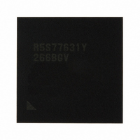
R5S77631Y266BGV Renesas Electronics America, R5S77631Y266BGV Datasheet - Page 1011

R5S77631Y266BGV
Manufacturer Part Number
R5S77631Y266BGV
Description
IC SUPERH MPU ROMLESS 499BGA
Manufacturer
Renesas Electronics America
Series
SuperH® SH7780r
Datasheet
1.R5S77631Y266BGV.pdf
(2056 pages)
Specifications of R5S77631Y266BGV
Core Processor
SH-4A
Core Size
32-Bit
Speed
266MHz
Connectivity
Audio Codec, I²C, MMC, SCI, SIM, SIO, SSI, USB
Peripherals
DMA, LCD, POR, WDT
Number Of I /o
107
Program Memory Type
ROMless
Ram Size
16K x 8
Voltage - Supply (vcc/vdd)
1.15 V ~ 1.35 V
Data Converters
A/D 4x10b; D/A 2x8b
Oscillator Type
External
Operating Temperature
-20°C ~ 75°C
Package / Case
499-BGA
Lead Free Status / RoHS Status
Lead free / RoHS Compliant
Eeprom Size
-
Program Memory Size
-
Available stocks
Company
Part Number
Manufacturer
Quantity
Price
Company:
Part Number:
R5S77631Y266BGV
Manufacturer:
Renesas Electronics America
Quantity:
10 000
- Current page: 1011 of 2056
- Download datasheet (10Mb)
Section 23 Gigabit Ethernet Controller (GETHER)
23.4.1
Descriptors and Descriptor List
The E-DMAC performs DMA transfer according to the information (data), referred to as a
descriptor, written in memory space. There are two types of descriptors: transmit descriptors and
receive descriptors. Before a DMA transfer, DMA transfer information including a
transmit/receive frame data storage address must be set by software.
The E-DMAC automatically starts reading a transmit/receive descriptor when the TR bits in
EDTRR are set to 11 or the RR bit in EDRRR is set to 1, and performs DMA transfer of frame
data between the transmit/receive buffer and transmit/receive FIFO according to the information
stored in the descriptor. After completion of Ethernet frame transmission/reception, the E-DMAC
disables the descriptor valid/invalid bit and reflects the result of transmission/reception in the
status bits.
Descriptors are placed in a readable/writable memory space. The address of the start descriptor
(descriptor to be read first by the E-DMAC) is set in TDLAR/RDLAR. When multiple descriptors
are prepared as a descriptor row (descriptor list), the descriptors are placed in continuous
addresses (memory) according to the descriptor length set in the DL0 and DL1 bits in EDMR.
The E-DMAC consists of two systems: one for port 0 and the other for port 1. The DMAC for
transmission and the DMAC for reception operate independently, and the DMAC for port 0 and
the DMAC for port 1 operate independently. Place descriptors for transmission and reception and
descriptors for port 0 and port 1 in those address spaces that do not overlap. If addresses are
overlapped, E-DMAC does not successfully operate.
(1)
Transmit Descriptor
Figure 23.3 shows the configuration of a transmit descriptor and the relationship with a transmit
buffer.
The data of a transmit descriptor consists of TD0, TD1, TD2, and padding data in groups of 32
bits from top to end. The length of padding data is determined according to the descriptor length
specified by the DL0 and DL1 bits in EDMR.
TD0 indicates whether the transmit descriptor is valid or invalid, and information about the
descriptor configuration and status. TD1 indicates the length of data in a transmit buffer to be
transferred (TDL) as specified by the descriptor. TD2 indicates the start address of a transmit
buffer that holds data to be transferred (TBA).
Depending on the descriptor specification, one transmit descriptor can specify all transmit data of
one frame (single-frame/single-buffer) or multiple descriptors can specify the transmit data of one
Rev. 2.00 May 22, 2009 Page 941 of 1982
REJ09B0256-0200
Related parts for R5S77631Y266BGV
Image
Part Number
Description
Manufacturer
Datasheet
Request
R

Part Number:
Description:
KIT STARTER FOR M16C/29
Manufacturer:
Renesas Electronics America
Datasheet:

Part Number:
Description:
KIT STARTER FOR R8C/2D
Manufacturer:
Renesas Electronics America
Datasheet:

Part Number:
Description:
R0K33062P STARTER KIT
Manufacturer:
Renesas Electronics America
Datasheet:

Part Number:
Description:
KIT STARTER FOR R8C/23 E8A
Manufacturer:
Renesas Electronics America
Datasheet:

Part Number:
Description:
KIT STARTER FOR R8C/25
Manufacturer:
Renesas Electronics America
Datasheet:

Part Number:
Description:
KIT STARTER H8S2456 SHARPE DSPLY
Manufacturer:
Renesas Electronics America
Datasheet:

Part Number:
Description:
KIT STARTER FOR R8C38C
Manufacturer:
Renesas Electronics America
Datasheet:

Part Number:
Description:
KIT STARTER FOR R8C35C
Manufacturer:
Renesas Electronics America
Datasheet:

Part Number:
Description:
KIT STARTER FOR R8CL3AC+LCD APPS
Manufacturer:
Renesas Electronics America
Datasheet:

Part Number:
Description:
KIT STARTER FOR RX610
Manufacturer:
Renesas Electronics America
Datasheet:

Part Number:
Description:
KIT STARTER FOR R32C/118
Manufacturer:
Renesas Electronics America
Datasheet:

Part Number:
Description:
KIT DEV RSK-R8C/26-29
Manufacturer:
Renesas Electronics America
Datasheet:

Part Number:
Description:
KIT STARTER FOR SH7124
Manufacturer:
Renesas Electronics America
Datasheet:

Part Number:
Description:
KIT STARTER FOR H8SX/1622
Manufacturer:
Renesas Electronics America
Datasheet:

Part Number:
Description:
KIT DEV FOR SH7203
Manufacturer:
Renesas Electronics America
Datasheet:


