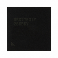
R5S77631Y266BGV Renesas Electronics America, R5S77631Y266BGV Datasheet - Page 51

R5S77631Y266BGV
Manufacturer Part Number
R5S77631Y266BGV
Description
IC SUPERH MPU ROMLESS 499BGA
Manufacturer
Renesas Electronics America
Series
SuperH® SH7780r
Datasheet
1.R5S77631Y266BGV.pdf
(2056 pages)
Specifications of R5S77631Y266BGV
Core Processor
SH-4A
Core Size
32-Bit
Speed
266MHz
Connectivity
Audio Codec, I²C, MMC, SCI, SIM, SIO, SSI, USB
Peripherals
DMA, LCD, POR, WDT
Number Of I /o
107
Program Memory Type
ROMless
Ram Size
16K x 8
Voltage - Supply (vcc/vdd)
1.15 V ~ 1.35 V
Data Converters
A/D 4x10b; D/A 2x8b
Oscillator Type
External
Operating Temperature
-20°C ~ 75°C
Package / Case
499-BGA
Lead Free Status / RoHS Status
Lead free / RoHS Compliant
Eeprom Size
-
Program Memory Size
-
Available stocks
Company
Part Number
Manufacturer
Quantity
Price
Company:
Part Number:
R5S77631Y266BGV
Manufacturer:
Renesas Electronics America
Quantity:
10 000
- Current page: 51 of 2056
- Download datasheet (10Mb)
Figure 28.23 BRG Block Diagram ........................................................................................... 1183
Section 29 Serial I/O with FIFO (SIOF)
Figure 29.1 Block Diagram of SIOF ........................................................................................ 1188
Figure 29.2 Serial Clock Supply............................................................................................... 1219
Figure 29.3 Serial Data Synchronization Timing ..................................................................... 1221
Figure 29.4 SIOF Transmit/Receive Timing ............................................................................ 1222
Figure 29.5 Transmit/Receive Data Bit Alignment .................................................................. 1225
Figure 29.6 Control Data Bit Alignment .................................................................................. 1226
Figure 29.7 Control Data Interface (Slot Position) ................................................................... 1228
Figure 29.8 Control Data Interface (Secondary FS) ................................................................. 1229
Figure 29.9 Example of Transmit Operation in Master Mode.................................................. 1231
Figure 29.10 Example of Receive Operation in Master Mode ................................................. 1232
Figure 29.11 Example of Transmit Operation in Slave Mode .................................................. 1233
Figure 29.12 Example of Receive Operation in Slave Mode.................................................... 1234
Figure 29.13 Transmit and Receive Timing (8-Bit Monaural Data (1))................................... 1238
Figure 29.14 Transmit and Receive Timing (8-Bit Monaural Data (2))................................... 1239
Figure 29.15 Transmit and Receive Timing (16-Bit Monaural Data)....................................... 1239
Figure 29.16 Transmit and Receive Timing (16-Bit Stereo Data (1)) ...................................... 1240
Figure 29.17 Transmit and Receive Timing (16-Bit Stereo Data (2)) ...................................... 1240
Figure 29.18 Transmit and Receive Timing (16-Bit Stereo Data (3)) ...................................... 1241
Figure 29.19 Transmit and Receive Timing (16-Bit Stereo Data (4)) ...................................... 1241
Figure 29.20 Transmit and Receive Timing (16-Bit Stereo Data)............................................ 1242
Section 30 SIM Card Module (SIM)
Figure 30.1 Smart Card Interface ............................................................................................. 1244
Figure 30.2 Data Format Used by Smart Card Interface .......................................................... 1268
Figure 30.3 Examples of Start Character Waveforms .............................................................. 1271
Figure 30.4 Example of Initialization Flow .............................................................................. 1273
Figure 30.5 Example of Transmit Processing........................................................................... 1275
Figure 30.6 Example of Receive Processing ............................................................................ 1277
Figure 30.7 Receive Data Sampling Timing in Smart Card Mode ........................................... 1280
Figure 30.8 Retransmission when Smart Card Interface is in Receive Mode........................... 1281
Figure 30.9 Retransmit Standby Mode (Clock Stopped) when Smart Card Interface is in
Transmit Mode ...................................................................................................... 1282
Figure 30.10 Procedure for Stopping Clock and Restarting ..................................................... 1283
Figure 30.11 Example of Pin Connections in Smart Card Interface......................................... 1284
Figure 30.12 TEIE Set Timing ................................................................................................. 1285
Rev. 2.00 May 22, 2009 Page xlix of lxviii
Related parts for R5S77631Y266BGV
Image
Part Number
Description
Manufacturer
Datasheet
Request
R

Part Number:
Description:
KIT STARTER FOR M16C/29
Manufacturer:
Renesas Electronics America
Datasheet:

Part Number:
Description:
KIT STARTER FOR R8C/2D
Manufacturer:
Renesas Electronics America
Datasheet:

Part Number:
Description:
R0K33062P STARTER KIT
Manufacturer:
Renesas Electronics America
Datasheet:

Part Number:
Description:
KIT STARTER FOR R8C/23 E8A
Manufacturer:
Renesas Electronics America
Datasheet:

Part Number:
Description:
KIT STARTER FOR R8C/25
Manufacturer:
Renesas Electronics America
Datasheet:

Part Number:
Description:
KIT STARTER H8S2456 SHARPE DSPLY
Manufacturer:
Renesas Electronics America
Datasheet:

Part Number:
Description:
KIT STARTER FOR R8C38C
Manufacturer:
Renesas Electronics America
Datasheet:

Part Number:
Description:
KIT STARTER FOR R8C35C
Manufacturer:
Renesas Electronics America
Datasheet:

Part Number:
Description:
KIT STARTER FOR R8CL3AC+LCD APPS
Manufacturer:
Renesas Electronics America
Datasheet:

Part Number:
Description:
KIT STARTER FOR RX610
Manufacturer:
Renesas Electronics America
Datasheet:

Part Number:
Description:
KIT STARTER FOR R32C/118
Manufacturer:
Renesas Electronics America
Datasheet:

Part Number:
Description:
KIT DEV RSK-R8C/26-29
Manufacturer:
Renesas Electronics America
Datasheet:

Part Number:
Description:
KIT STARTER FOR SH7124
Manufacturer:
Renesas Electronics America
Datasheet:

Part Number:
Description:
KIT STARTER FOR H8SX/1622
Manufacturer:
Renesas Electronics America
Datasheet:

Part Number:
Description:
KIT DEV FOR SH7203
Manufacturer:
Renesas Electronics America
Datasheet:


