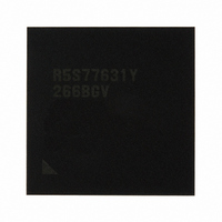
R5S77631Y266BGV Renesas Electronics America, R5S77631Y266BGV Datasheet - Page 49

R5S77631Y266BGV
Manufacturer Part Number
R5S77631Y266BGV
Description
IC SUPERH MPU ROMLESS 499BGA
Manufacturer
Renesas Electronics America
Series
SuperH® SH7780r
Datasheet
1.R5S77631Y266BGV.pdf
(2056 pages)
Specifications of R5S77631Y266BGV
Core Processor
SH-4A
Core Size
32-Bit
Speed
266MHz
Connectivity
Audio Codec, I²C, MMC, SCI, SIM, SIO, SSI, USB
Peripherals
DMA, LCD, POR, WDT
Number Of I /o
107
Program Memory Type
ROMless
Ram Size
16K x 8
Voltage - Supply (vcc/vdd)
1.15 V ~ 1.35 V
Data Converters
A/D 4x10b; D/A 2x8b
Oscillator Type
External
Operating Temperature
-20°C ~ 75°C
Package / Case
499-BGA
Lead Free Status / RoHS Status
Lead free / RoHS Compliant
Eeprom Size
-
Program Memory Size
-
Available stocks
Company
Part Number
Manufacturer
Quantity
Price
Company:
Part Number:
R5S77631Y266BGV
Manufacturer:
Renesas Electronics America
Quantity:
10 000
- Current page: 49 of 2056
- Download datasheet (10Mb)
Figure 23.36 Independent Bus Release Flowchart (IDLE in Write in Figure 23.33) ................. 993
Figure 23.37 MII-RMII Conversion Circuit ............................................................................... 994
Figure 23.38 Data Subject to Checksum Calculation ................................................................. 995
Section 25 Stream Interface (STIF)
Figure 25.1 Block Diagram of STIF ......................................................................................... 1000
Figure 25.2 Transmit/Receive Data Structure in External Memory
Figure 25.3 Clock Valid Reception Timing.............................................................................. 1019
Figure 25.4 Strobe Reception Timing....................................................................................... 1021
Figure 25.5 Clock Valid Transmission Timing ........................................................................ 1023
Figure 25.6 Strobe Transmission Timing ................................................................................. 1025
Section 26 I
Figure 26.1 Block Diagram for I
Figure 26.2 I
Figure 26.3 Master Data Transmit Format ............................................................................... 1049
Figure 26.4 Master Data Receive Format ................................................................................. 1049
Figure 26.5 Combination Transfer Format of Master Transfer ................................................ 1050
Figure 26.6 10-Bit Address Data Transmit Format .................................................................. 1050
Figure 26.7 10-Bit Address Data Receive Format.................................................................... 1051
Figure 26.8 10-Bit Address Transmit/Receive Combined Format ........................................... 1051
Figure 26.9 Data Transmit Mode Operation Timing ................................................................ 1053
Figure 26.10 Data Receive Mode Operation Timing................................................................ 1055
Section 27 Serial Communication Interface with FIFO (SCIF)
Figure 27.1 Block Diagram of SCIF......................................................................................... 1063
Figure 27.2 SCIFn_RTS Pin (n = 0, 1) ..................................................................................... 1064
Figure 27.3 SCIFn_CTS Pin (n = 0, 1) ..................................................................................... 1065
Figure 27.4 SCIFn_SCK Pin (n = 0, 1)..................................................................................... 1066
Figure 27.5 SCIFn_TXD Pin (n = 0, 1) .................................................................................... 1066
Figure 27.6 SCIFn_RXD Pin (n = 0, 1).................................................................................... 1067
Figure 27.7 Data Format in Asynchronous Communication
Figure 27.8 Sample SCIF Initialization Flowchart ................................................................... 1099
Figure 27.9 Sample Serial Transmission Flowchart ................................................................. 1100
Figure 27.10 Sample SCIF Transmission Operation
Figure 27.11 Sample Operation Using Modem Control (SCIF_CTS)...................................... 1102
Figure 27.12 Sample Serial Reception Flowchart (1)............................................................... 1103
Figure 27.12 Sample Serial Reception Flowchart (2)............................................................... 1104
(with 16-Byte Work Area)..................................................................................... 1017
(Example with 8-Bit Data, Parity, and Two Stop Bits) ......................................... 1096
2
2
C Bus Interface (IIC)
(Example with 8-Bit Data, Parity, One Stop Bit) ................................................ 1102
C Bus Timing...................................................................................................... 1048
2
C Bus Interface .................................................................... 1027
Rev. 2.00 May 22, 2009 Page xlvii of lxviii
Related parts for R5S77631Y266BGV
Image
Part Number
Description
Manufacturer
Datasheet
Request
R

Part Number:
Description:
KIT STARTER FOR M16C/29
Manufacturer:
Renesas Electronics America
Datasheet:

Part Number:
Description:
KIT STARTER FOR R8C/2D
Manufacturer:
Renesas Electronics America
Datasheet:

Part Number:
Description:
R0K33062P STARTER KIT
Manufacturer:
Renesas Electronics America
Datasheet:

Part Number:
Description:
KIT STARTER FOR R8C/23 E8A
Manufacturer:
Renesas Electronics America
Datasheet:

Part Number:
Description:
KIT STARTER FOR R8C/25
Manufacturer:
Renesas Electronics America
Datasheet:

Part Number:
Description:
KIT STARTER H8S2456 SHARPE DSPLY
Manufacturer:
Renesas Electronics America
Datasheet:

Part Number:
Description:
KIT STARTER FOR R8C38C
Manufacturer:
Renesas Electronics America
Datasheet:

Part Number:
Description:
KIT STARTER FOR R8C35C
Manufacturer:
Renesas Electronics America
Datasheet:

Part Number:
Description:
KIT STARTER FOR R8CL3AC+LCD APPS
Manufacturer:
Renesas Electronics America
Datasheet:

Part Number:
Description:
KIT STARTER FOR RX610
Manufacturer:
Renesas Electronics America
Datasheet:

Part Number:
Description:
KIT STARTER FOR R32C/118
Manufacturer:
Renesas Electronics America
Datasheet:

Part Number:
Description:
KIT DEV RSK-R8C/26-29
Manufacturer:
Renesas Electronics America
Datasheet:

Part Number:
Description:
KIT STARTER FOR SH7124
Manufacturer:
Renesas Electronics America
Datasheet:

Part Number:
Description:
KIT STARTER FOR H8SX/1622
Manufacturer:
Renesas Electronics America
Datasheet:

Part Number:
Description:
KIT DEV FOR SH7203
Manufacturer:
Renesas Electronics America
Datasheet:


